- 您现在的位置:买卖IC网 > PDF目录11022 > LTC1164ACSW#PBF (Linear Technology)IC FILTER BUILDING BLOCK 24-SOIC PDF资料下载
参数资料
| 型号: | LTC1164ACSW#PBF |
| 厂商: | Linear Technology |
| 文件页数: | 2/16页 |
| 文件大小: | 0K |
| 描述: | IC FILTER BUILDING BLOCK 24-SOIC |
| 标准包装: | 32 |
| 滤波器类型: | 通用开关电容器 |
| 频率 - 截止或中心: | 20kHz |
| 滤波器数: | 4 |
| 滤波器阶数: | 8th |
| 电源电压: | ±2.37 V ~ 8 V |
| 安装类型: | 表面贴装 |
| 封装/外壳: | 24-SOIC(0.295",7.50mm 宽) |
| 供应商设备封装: | 24-SOIC |
| 包装: | 管件 |
LTC1164
10
1164fa
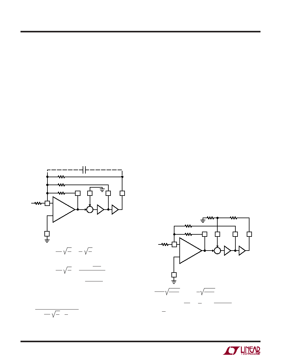
Mode 3
Mode 3 is the second of the primary modes. In Mode 3, the
ratio of the external clock frequency to the center
frequency of each 2nd order section can be adjusted above
or below 50:1 or 100:1. Side D of the LTC1164 can only be
connected in Mode 3. Figure 7 illustrates Mode 3, the
classical state variable configuration, providing highpass,
bandpass, and lowpass 2nd order filter functions. Mode 3
is slower than Mode 1. Mode 3 can be used to make high
order all-pole bandpass, lowpass, highpass and notch
filters.
When the internal clock-to-center frequency ratio is set at
50:1, the design equations for Q and bandpass gain are
different from the 100:1 case. This was done to provide
speed without penalizing the noise performance.
SECONDARY MODES
Mode 1b
Mode 1b is derived from Mode 1. In Mode 1b, Figure 8, two
additional resistors R5 and R6, are added to alternate the
amount of voltage feedback from the lowpass output into
the input of the SA (or SB or SC) switched capacitor
summer. This allows the filter clock-to-center frequency
ratio to be adjusted beyond 50:1 or 100:1. Mode 1b
maintains the speed advantages of Mode 1.
Mode 2
Mode 2 is a combination of Mode 1 and Mode 3, as shown
in Figure 9. With Mode 2, the clock-to-center frequency
ratio, fCLK/fO, is always less than 50:1 or 100:1. The
advantage of Mode 2 is that it provides less sensitivity to
resistor tolerances than does Mode 3. As in Mode 1,
Mode 2 has a notch output which depends on the clock
frequency, and the notch frequency is therefore less than
the center frequency, fO.
When the internal clock-to-center frequency ratio is set at
50:1, the design equations for Q and bandpass gain are
different from the 100:1 case.
Figure 8. Mode 1b: 2nd Order Filter Providing Notch,
Bandpass, Lowpass
Figure 7. Mode 3: 2nd Order Filter Providing Highpass,
Bandpass, Lowpass
LTC1164 MOO02
R3
R4
R2
HP
S
BP
LP
R1
AGND
R2/R1;
1/4 LTC1164
fo =
; Q =
; HOHP = –
R3/R1;
HOBP = –
MODE 3 (100:1):
R4/R1
HOLP = –
R4/R1
; HOLP = –
R2/R1;
HOLP = –
fCLK
100
–
+
–
Σ
∫
VIN
CC
R3
R2
R4
fo =
; Q =
MODE 3 (50:1):
; THEN CALCULATE R1 TO SET
THE DESIRED GAIN
R3 =
R2
NOTE: THE 50:1 EQUATIONS FOR MODE 3 ARE DIFFERENT FROM THE EQUATIONS
FOR MODE 3 OPERATION OF THE LTC1059, LTC1060 AND LTC1061. START WITH
fo, CALCULATE R2/R4, SET R4; FROM THE Q VALUE, CALCULATE R3:
fCLK
50
R2
R4
R2
R4
R3/R1
1 – (R3/16R4)
1.005 (√R2/R4)
(R2/R3) – (R2/16R4);
+
1.005
Q
R2
R4
R2
16R4
LTC1164 MOO03
R3
R6
R5
R2
NS
BP
LP
R1
AGND
fo =
; Q =
= –
;
; (R5//R6) < 5k
HON1 (f → 0) = HON2 f →
HOBP = –
; HOLP =;
fCLK
100(50)
–
+
–
Σ
∫
VIN
fCLK
2
R3
R2
R3
R1
R2
R1
; fn = fo
R6
R5 + R6
– R2/R1
R6/(R5 + R6)
R6
R5 + R6
()
ODES OF OPERATIO
U
W
相关PDF资料 |
PDF描述 |
|---|---|
| LTC1164ACSW | IC FILTER BUILDING BLOCK 24-SOIC |
| MC9S08JS8LCFK | MCU 8BIT 8K FLASH 24-QFN |
| MC9S08QG8MFQE | IC MCU 8K FLASH 8-DFN |
| JBXER1G10FSSDPR | CONN RCPT 10POS FRONT MNT SOLDER |
| LTC1164CN | IC FILTER BUILDING BLOCK 24-DIP |
相关代理商/技术参数 |
参数描述 |
|---|---|
| LTC1164AM | 制造商:LINER 制造商全称:Linear Technology 功能描述:Low Power, Low Noise, Quad Universal Filter Building Block |
| LTC1164AMJ | 制造商:Linear Technology 功能描述:Active Filter Quad SW-CAP UNIV 8th Order 20kHz 24-Pin CDIP |
| LTC1164C | 制造商:LINER 制造商全称:Linear Technology 功能描述:Low Power, Low Noise, Quad Universal Filter Building Block |
| LTC1164CJ | 制造商:Linear Technology 功能描述:Active Filter Quad SW-CAP UNIV 8th Order 20kHz 24-Pin CDIP |
| LTC1164CN | 功能描述:IC FILTER BUILDING BLOCK 24-DIP RoHS:否 类别:集成电路 (IC) >> 接口 - 滤波器 - 有源 系列:- 产品培训模块:Lead (SnPb) Finish for COTS Obsolescence Mitigation Program 标准包装:1,000 系列:- 滤波器类型:连续时间,带通低通 频率 - 截止或中心:150kHz 滤波器数:4 滤波器阶数:8th 电源电压:4.74 V ~ 11 V,±2.37 V ~ 5.5 V 安装类型:表面贴装 封装/外壳:28-SOIC(0.295",7.50mm 宽) 供应商设备封装:28-SOIC W 包装:带卷 (TR) |
发布紧急采购,3分钟左右您将得到回复。