- 您现在的位置:买卖IC网 > PDF目录16037 > LTC1730ES8-4.2 (Linear Technology)IC BATT PULSE CHRGR LI-ION 8SOIC PDF资料下载
参数资料
| 型号: | LTC1730ES8-4.2 |
| 厂商: | Linear Technology |
| 文件页数: | 9/12页 |
| 文件大小: | 0K |
| 描述: | IC BATT PULSE CHRGR LI-ION 8SOIC |
| 标准包装: | 100 |
| 功能: | 充电管理 |
| 电池化学: | 锂离子(Li-Ion) |
| 电源电压: | 4.5 V ~ 12 V |
| 工作温度: | -40°C ~ 85°C |
| 安装类型: | 表面贴装 |
| 封装/外壳: | 8-SOIC(0.154",3.90mm 宽) |
| 供应商设备封装: | 8-SOIC |
| 包装: | 管件 |
�� �
�
�LTC1730-4/LTC1730-4.2�
�APPLICATIO� S� I� FOR� ATIO�
�End-of-Charge� (C/10)�
�The� LTC1730� includes� a� comparator� to� monitor� the� duty�
�cycle� at� the� GATE� pin� to� detect� a� near� end-of-charge�
�V� CC�
�10� μ� A/C�
�40� μ� A/C�
�40� μ� A/C�
�condition.� When� the� duty� cycle� falls� below� 10%,� the�
�comparator� trips� and� turns� off� the� N-MOSFET� at� the� CHRG�
�pin� and� switches� in� a� weak� (40� μ� A)� current� source� to�
�ground.� The� end-of-charge� comparator� is� disabled� in�
�trickle� charge� mode.�
�GATE�
�VOLTAGE�
�10� μ� A/C�
�10� μ� A/C 40� μ� A/C�
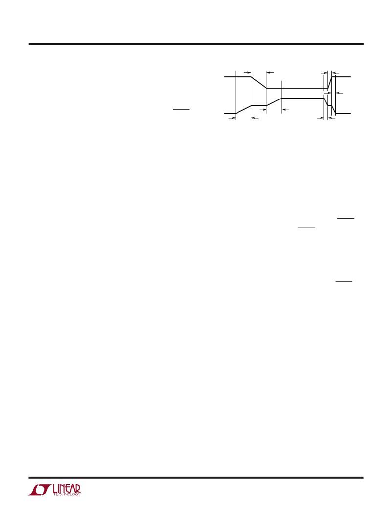
�Figure� 2.� Slew� Rate� at� GATE� and� V� CC� Pins�
�with� the� RC� Network� from� GATE� to� V� CC�
�1730� TA02�
�Internal� Pass� Transistor�
�An� N-channel� MOSFET� (0.35� ?� )� is� included� in� the� LTC1730�
�as� the� pass� transistor.� The� gate� of� the� MOSFET� is� con-�
�trolled� by� an� internal� charge� pump.� The� body� is� connected�
�to� ground� instead� of� source� terminal.� There� is� no� body�
�diode� from� the� BAT� pin� back� to� the� V� CC� pin;� therefore,� no�
�blocking� diode� is� required� in� series� with� the� battery� or� the�
�input� supply.� This� will� not� only� reduce� the� cost� but� also� the�
�heat� generated� when� in� fast� charge� mode.� An� internal�
�thermal� shutdown� circuit� turns� off� the� pass� transistor� if�
�the� die� temperature� exceeds� approximately� 140� °� C� with�
�5� °� C� of� thermal� hysteresis.�
�Gate� Drive�
�The� pass� transistor� gate� drive� consists� of� a� regulated� 10� μ� A�
�current� source� charge� pump.� A� series� RC� network� is�
�required� from� the� GATE� pin� to� the� V� CC� pin.� When� the� pass�
�transistor� is� turned� on,� the� voltage� at� the� V� CC� pin� starts�
�slewing� down� to� a� voltage� equal� to� V� BAT� plus� the� voltage�
�drop� across� the� pass� transistor� and� R� SENSE� .� The� slew� rate�
�is� equal� to� 10� μ� A/C.� By� ramping� the� V� CC� pin� down� slowly,�
�the� inrush� current� is� reduced.� The� resistor� in� series� with�
�the� capacitor� is� required� to� limit� the� transient� current� when�
�the� input� supply� is� first� applied.�
�When� the� charge� pump� is� turned� off,� a� 40� μ� A� current�
�source� to� ground� starts� pulling� the� GATE� voltage� down.�
�Once� the� pass� transistor� is� off,� the� voltage� at� the� V� CC� pin�
�begins� slewing� up� with� the� rate� equal� to� 40� μ� A/C.� With� this�
�external� capacitor,� the� voltage� at� the� V� CC� pin� is� ramping� at�
�a� controlled� manner� (Figure� 2).�
�For� higher� current� applications� an� external� power� N-MOSFET�
�can� be� connected� in� parallel� with� the� internal� pass� transis-�
�tor.� Because� the� charge� pump� output� is� clamped� to� 12V�
�above� V� BAT� ,� the� external� N-MOSFET� gate� to� source� break-�
�down� voltage� should� be� rated� at� 20V� or� more.�
�Battery� Temperature� Detection�
�A� negative� temperature� coefficient� (NTC)� thermistor� lo-�
�cated� close� to� the� battery� pack� can� be� used� to� monitor�
�battery� temperature� and� will� not� allow� charging� unless� the�
�battery� temperature� is� within� an� acceptable� range.� Connect�
�a� 10k� ?� thermistor� between� ground� and� the� NTC/SHDN� pin�
�and� a� 4.1k� resistor� from� the� NTC/SHDN� pin� to� V� CC� .� If� the�
�temperature� rises� to� 50� °� C,� the� resistance� of� the� thermister�
�will� be� approximately� 4.1k� ?� (Dale� NTHS-1206N02)� and�
�the� LTC1730� will� go� into� a� hold� mode.� For� cold� tempera-�
�tures,� the� threshold� of� the� hold� mode� is� at� 0� °� C� (R� NTC� ≈�
�28k� ?� ).� The� pass� transistor� turns� off� and� the� timer� is� frozen�
�at� hold� mode� while� the� output� status� at� the� CHRG� pin�
�remains� the� same.� The� charge� cycle� begins� or� resumes�
�once� the� temperature� is� within� the� acceptable� range.�
�Thermal� Considerations�
�The� power� handling� capability� is� limited� by� the� maximum�
�rated� junction� temperature� (125� °� C)� and� the� amount� of� PC�
�board� copper� used� as� a� heat� sink.� The� power� dissipated� by�
�the� device� consists� of� two� components:�
�1.� Input� supply� current� multiplied� by� the� input� voltage�
�2.� The� voltage� drop� across� the� switch� (SENSE� pin� to� BAT�
�pin)� multiplied� by� the� charge� current�
�The� LTC1730� has� internal� thermal� shutdown� designed� to�
�protect� the� IC� from� overtemperature� conditions.� For� con-�
�tinuous� charging� in� the� fast� charge� mode,� the� maximum�
�junction� temperature� must� not� be� exceeded.� It� is� important�
�to� give� careful� consideration� to� all� sources� of� thermal�
�resistance� from� junction� to� ambient.� Additional� heat� sources�
�mounted� nearby� must� also� be� considered.�
�sn1730� 1730fs�
�9�
�相关PDF资料 |
PDF描述 |
|---|---|
| GBM18DTBI-S189 | CONN EDGECARD 36POS R/A .156 SLD |
| A3BRB-5018M | IDC CABLE - ASR50B/AE50M/APR50B |
| M3DYK-4018R | IDC CABLE - MKR40K/MC40M/MPD40K |
| M3BYK-4018R | IDC CABLE - MSR40K/MC40M/MPD40K |
| RCM10DTMS-S189 | CONN EDGECARD 20POS R/A .156 SLD |
相关代理商/技术参数 |
参数描述 |
|---|---|
| LTC1731EMS8-4.1 | 功能描述:IC CTRLR BATT CHRGR LI-ION 8MSOP RoHS:否 类别:集成电路 (IC) >> PMIC - 电池管理 系列:- 标准包装:61 系列:- 功能:电源管理 电池化学:锂离子(Li-Ion)、锂聚合物(Li-Pol) 电源电压:4.35 V ~ 5.5 V 工作温度:-40°C ~ 85°C 安装类型:表面贴装 封装/外壳:22-WFDFN 裸露焊盘 供应商设备封装:22-DFN(6x3)裸露焊盘 包装:管件 |
| LTC1731EMS8-4.1#PBF | 功能描述:IC CTRLR BATT CHRGR LI-ION 8MSOP RoHS:是 类别:集成电路 (IC) >> PMIC - 电池管理 系列:- 标准包装:61 系列:- 功能:电源管理 电池化学:锂离子(Li-Ion)、锂聚合物(Li-Pol) 电源电压:4.35 V ~ 5.5 V 工作温度:-40°C ~ 85°C 安装类型:表面贴装 封装/外壳:22-WFDFN 裸露焊盘 供应商设备封装:22-DFN(6x3)裸露焊盘 包装:管件 |
| LTC1731EMS8-4.1#TR | 功能描述:IC CTRLR BATT CHRGR LI-ION 8MSOP RoHS:否 类别:集成电路 (IC) >> PMIC - 电池管理 系列:- 标准包装:61 系列:- 功能:电源管理 电池化学:锂离子(Li-Ion)、锂聚合物(Li-Pol) 电源电压:4.35 V ~ 5.5 V 工作温度:-40°C ~ 85°C 安装类型:表面贴装 封装/外壳:22-WFDFN 裸露焊盘 供应商设备封装:22-DFN(6x3)裸露焊盘 包装:管件 |
| LTC1731EMS8-4.1#TRPBF | 功能描述:IC CTRLR BATT CHRGR LI-ION 8MSOP RoHS:是 类别:集成电路 (IC) >> PMIC - 电池管理 系列:- 标准包装:61 系列:- 功能:电源管理 电池化学:锂离子(Li-Ion)、锂聚合物(Li-Pol) 电源电压:4.35 V ~ 5.5 V 工作温度:-40°C ~ 85°C 安装类型:表面贴装 封装/外壳:22-WFDFN 裸露焊盘 供应商设备封装:22-DFN(6x3)裸露焊盘 包装:管件 |
| LTC1731EMS8-4.2 | 功能描述:IC CTRLR BATT CHRGR LI-ION 8MSOP RoHS:否 类别:集成电路 (IC) >> PMIC - 电池管理 系列:- 标准包装:61 系列:- 功能:电源管理 电池化学:锂离子(Li-Ion)、锂聚合物(Li-Pol) 电源电压:4.35 V ~ 5.5 V 工作温度:-40°C ~ 85°C 安装类型:表面贴装 封装/外壳:22-WFDFN 裸露焊盘 供应商设备封装:22-DFN(6x3)裸露焊盘 包装:管件 |
发布紧急采购,3分钟左右您将得到回复。