- 您现在的位置:买卖IC网 > PDF目录44988 > LTC1871HMS (LINEAR TECHNOLOGY CORP) 0.05 A SWITCHING CONTROLLER, 1000 kHz SWITCHING FREQ-MAX, PDSO10 PDF资料下载
参数资料
| 型号: | LTC1871HMS |
| 厂商: | LINEAR TECHNOLOGY CORP |
| 元件分类: | 稳压器 |
| 英文描述: | 0.05 A SWITCHING CONTROLLER, 1000 kHz SWITCHING FREQ-MAX, PDSO10 |
| 封装: | PLASTIC, MSOP-10 |
| 文件页数: | 9/36页 |
| 文件大小: | 519K |
| 代理商: | LTC1871HMS |
第1页第2页第3页第4页第5页第6页第7页第8页当前第9页第10页第11页第12页第13页第14页第15页第16页第17页第18页第19页第20页第21页第22页第23页第24页第25页第26页第27页第28页第29页第30页第31页第32页第33页第34页第35页第36页
LTC1871
17
1871fe
APPLICATIONS INFORMATION
Remember to keep the diode lead lengths short and to
observe proper switch-node layout (see Board Layout
Checklist) to avoid excessive ringing and increased dis-
sipation.
Boost Converter: Output Capacitor Selection
Contributions of ESR (equivalent series resistance), ESL
(equivalent series inductance) and the bulk capacitance
must be considered when choosing the correct component
for a given output ripple voltage. The effects of these three
parameters (ESR, ESL and bulk C) on the output voltage
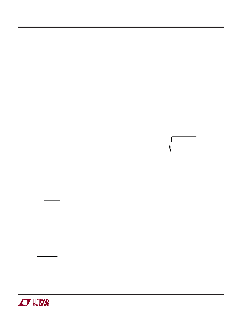
ripple waveform are illustrated in Figure 12e for a typical
boost converter.
The choice of component(s) begins with the maximum
acceptable ripple voltage (expressed as a percentage of
the output voltage), and how this ripple should be divided
between the ESR step and the charging/discharging ΔV.
For the purpose of simplicity we will choose 2% for the
maximum output ripple, to be divided equally between the
ESR step and the charging/discharging ΔV. This percent-
age ripple will change, depending on the requirements
of the application, and the equations provided below can
easily be modied.
For a 1% contribution to the total ripple voltage, the ESR
of the output capacitor can be determined using the fol-
lowing equation:
ESRCOUT
0.01 VO
IIN(PEAK)
where:
IIN(PEAK)= 1+
2
IO(MAX)
1– DMAX
For the bulk C component, which also contributes 1% to
the total ripple:
COUT
IO(MAX)
0.01 VO f
For many designs it is possible to choose a single capacitor
type that satises both the ESR and bulk C requirements
for the design. In certain demanding applications, however,
the ripple voltage can be improved signicantly by con-
necting two or more types of capacitors in parallel. For
example, using a low ESR ceramic capacitor can minimize
the ESR step, while an electrolytic capacitor can be used
to supply the required bulk C.
Once the output capacitor ESR and bulk capacitance have
been determined, the overall ripple voltage waveform
should be veried on a dedicated PC board (see Board
Layout section for more information on component place-
ment). Lab breadboards generally suffer from excessive
series inductance (due to inter-component wiring), and
these parasitics can make the switching waveforms look
signicantly worse than they would be on a properly
designed PC board.
The output capacitor in a boost regulator experiences high
RMS ripple currents, as shown in Figure 12. The RMS
output capacitor ripple current is:
IRMS(COUT) IO(MAX)
VO –VIN(MIN)
VIN(MIN)
Note that the ripple current ratings from capacitor manu-
facturers are often based on only 2000 hours of life. This
makes it advisable to further derate the capacitor or to
choose a capacitor rated at a higher temperature than
required. Several capacitors may also be placed in parallel
to meet size or height requirements in the design.
Manufacturers such as Nichicon, United Chemicon and
Sanyo should be considered for high performance through-
hole capacitors. The OS-CON semiconductor dielectric
capacitor available from Sanyo has the lowest product of
ESR and size of any aluminum electrolytic, at a somewhat
higher price.
In surface mount applications, multiple capacitors may
have to be placed in parallel in order to meet the ESR or
RMS current handling requirements of the application.
Aluminum electrolytic and dry tantalum capacitors are
both available in surface mount packages. In the case of
tantalum, it is critical that the capacitors have been surge
tested for use in switching power supplies. An excellent
choice is AVX TPS series of surface mount tantalum. Also,
ceramic capacitors are now available with extremely low
ESR, ESL and high ripple current ratings.
相关PDF资料 |
PDF描述 |
|---|---|
| LTC1877IMS8#TRPBF | 1.5 A SWITCHING REGULATOR, 605 kHz SWITCHING FREQ-MAX, PDSO8 |
| LTC1929IG-PG | 3 A DUAL SWITCHING CONTROLLER, 310 kHz SWITCHING FREQ-MAX, PDSO28 |
| LTC203MJ/883B | QUAD 1-CHANNEL, SGL POLE SGL THROW SWITCH, CDIP16 |
| LTC202MJ/883B | QUAD 1-CHANNEL, SGL POLE SGL THROW SWITCH, CDIP16 |
| LTC201AMJ/883B | QUAD 1-CHANNEL, SGL POLE SGL THROW SWITCH, CDIP16 |
相关代理商/技术参数 |
参数描述 |
|---|---|
| LTC1871HMS#PBF | 功能描述:IC REG CTRLR BST FLYBK CM 10MSOP RoHS:是 类别:集成电路 (IC) >> PMIC - 稳压器 - DC DC 切换控制器 系列:- 标准包装:2,500 系列:- PWM 型:电流模式 输出数:1 频率 - 最大:500kHz 占空比:96% 电源电压:4 V ~ 36 V 降压:无 升压:是 回扫:无 反相:无 倍增器:无 除法器:无 Cuk:无 隔离:无 工作温度:-40°C ~ 125°C 封装/外壳:24-WQFN 裸露焊盘 包装:带卷 (TR) |
| LTC1871HMS#TRPBF | 功能描述:IC REG CTRLR BST FLYBK CM 10MSOP RoHS:是 类别:集成电路 (IC) >> PMIC - 稳压器 - DC DC 切换控制器 系列:- 标准包装:2,500 系列:- PWM 型:电流模式 输出数:1 频率 - 最大:500kHz 占空比:96% 电源电压:4 V ~ 36 V 降压:无 升压:是 回扫:无 反相:无 倍增器:无 除法器:无 Cuk:无 隔离:无 工作温度:-40°C ~ 125°C 封装/外壳:24-WQFN 裸露焊盘 包装:带卷 (TR) |
| LTC1871HMSPBF | 制造商:Linear Technology 功能描述:PWM Controller Current Mode MSOP10 |
| LTC1871IMS | 功能描述:IC REG CTRLR BST FLYBK CM 10MSOP RoHS:否 类别:集成电路 (IC) >> PMIC - 稳压器 - DC DC 切换控制器 系列:- 标准包装:2,500 系列:- PWM 型:电流模式 输出数:1 频率 - 最大:500kHz 占空比:96% 电源电压:4 V ~ 36 V 降压:无 升压:是 回扫:无 反相:无 倍增器:无 除法器:无 Cuk:无 隔离:无 工作温度:-40°C ~ 125°C 封装/外壳:24-WQFN 裸露焊盘 包装:带卷 (TR) |
| LTC1871IMS#PBF | 功能描述:IC REG CTRLR BST FLYBK CM 10MSOP RoHS:是 类别:集成电路 (IC) >> PMIC - 稳压器 - DC DC 切换控制器 系列:- 标准包装:2,500 系列:- PWM 型:电流模式 输出数:1 频率 - 最大:500kHz 占空比:96% 电源电压:4 V ~ 36 V 降压:无 升压:是 回扫:无 反相:无 倍增器:无 除法器:无 Cuk:无 隔离:无 工作温度:-40°C ~ 125°C 封装/外壳:24-WQFN 裸露焊盘 包装:带卷 (TR) |
发布紧急采购,3分钟左右您将得到回复。