- 您现在的位置:买卖IC网 > PDF目录14888 > LTC3405ES6#TRMPBF (Linear Technology)IC REG BUCK SYNC ADJ .3A SOT23-6 PDF资料下载
参数资料
| 型号: | LTC3405ES6#TRMPBF |
| 厂商: | Linear Technology |
| 文件页数: | 8/16页 |
| 文件大小: | 0K |
| 描述: | IC REG BUCK SYNC ADJ .3A SOT23-6 |
| 标准包装: | 1 |
| 类型: | 降压(降压) |
| 输出类型: | 可调式 |
| 输出数: | 1 |
| 输出电压: | 0.8 V ~ 6 V |
| 输入电压: | 2.5 V ~ 5.5 V |
| PWM 型: | 电流模式,混合 |
| 频率 - 开关: | 1.5MHz |
| 电流 - 输出: | 300mA |
| 同步整流器: | 是 |
| 工作温度: | -40°C ~ 85°C |
| 安装类型: | 表面贴装 |
| 封装/外壳: | SOT-23-6 细型,TSOT-23-6 |
| 包装: | 标准包装 |
| 供应商设备封装: | TSOT-23-6 |
| 产品目录页面: | 1334 (CN2011-ZH PDF) |
| 其它名称: | LTC3405ES6#TRMPBFDKR |
�� �
�
�LTC3405�
�APPLICATIO� S� I� FOR� ATIO�
�The� basic� LTC3405� application� circuit� is� shown� in� Figure� 1.�
�External� component� selection� is� driven� by� the� load� require-�
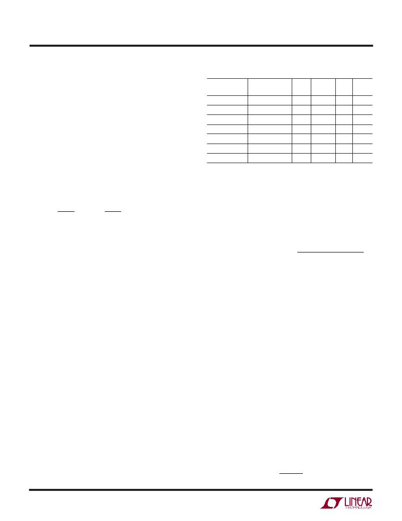
�Table� 1.� Representative� Surface� Mount� Inductors�
�MAX� DC�
�ment� and� begins� with� the� selection� of� L� followed� by� C� IN� and�
�C� OUT� .�
�MANUFACTURER� PART� NUMBER�
�Taiyo� Yuden� LB2016T3R3M�
�Panasonic� ELT5KT4R7M�
�VALUE� CURRENT� DCR� HEIGHT�
�3.3� μ� H� 280mA� 0.2� ?� 1.6mm�
�4.7� μ� H� 950mA� 0.2� ?� 1.2mm�
�Inductor� Selection�
�Murata�
�LQH3C4R7M34�
�4.7� μ� H�
�450mA�
�0.2� ?�
�2mm�
�For� most� applications,� the� value� of� the� inductor� will� fall� in�
�the� range� of� 3.3� μ� H� to� 10� μ� H.� Its� value� is� chosen� based� on�
�the� desired� ripple� current.� Large� value� inductors� lower�
�Taiyo� Yuden�
�Panasonic�
�Panasonic�
�LB2016T4R7M�
�ELT5KT6R8M�
�ELT5KT100M�
�4.7� μ� H�
�6.8� μ� H�
�10� μ� H�
�210mA�
�760mA�
�680mA�
�0.25� ?� 1.6mm�
�0.3� ?� 1.2mm�
�0.36� ?� 1.2mm�
�ripple� current� and� small� value� inductors� result� in� higher�
�Sumida�
�CMD4D116R8MC� 6.8� μ� H�
�620mA�
�0.23� ?� 1.2mm�
�ripple� currents.� Higher� V� IN� or� V� OUT� also� increases� the� ripple�
�current� as� shown� in� equation� 1.� A� reasonable� starting� point�
�for� setting� ripple� current� is� ?� I� L� =� 120mA� (40%� of� 300mA).�
�C� IN� and� C� OUT� Selection�
�In� continuous� mode,� the� source� current� of� the� top� MOSFET�
�V� OUT� ?� 1� ?� OUT� ?�
�?� I� L� =�
�1�
�(� f� )(� L� )�
�?� V� ?�
�?� V� IN� ?�
�(1)�
�is� a� square� wave� of� duty� cycle� V� OUT� /V� IN� .� To� prevent� large�
�voltage� transients,� a� low� ESR� input� capacitor� sized� for� the�
�maximum� RMS� current� must� be� used.� The� maximum�
�RMS� capacitor� current� is� given� by:�
�The� DC� current� rating� of� the� inductor� should� be� at� least�
�equal� to� the� maximum� load� current� plus� half� the� ripple�
�current� to� prevent� core� saturation.� Thus,� a� 360mA� rated�
�inductor� should� be� enough� for� most� applications� (300mA�
�C� IN� required� I� RMS� ?� I� OMAX�
�[� V� OUT� (� V� IN� ?� V� OUT� )� ]� 1� /� 2�
�V� IN�
�+� 60mA).� For� better� efficiency,� choose� a� low� DC-resistance�
�inductor.�
�The� inductor� value� also� has� an� effect� on� Burst� Mode�
�operation.� The� transition� to� low� current� operation� begins�
�when� the� inductor� current� peaks� fall� to� approximately�
�100mA.� Lower� inductor� values� (higher� ?� I� L� )� will� cause� this�
�to� occur� at� lower� load� currents,� which� can� cause� a� dip� in�
�efficiency� in� the� upper� range� of� low� current� operation.� In�
�Burst� Mode� operation,� lower� inductance� values� will� cause�
�the� burst� frequency� to� increase.�
�Inductor� Core� Selection�
�Different� core� materials� and� shapes� will� change� the� size/�
�current� and� price/current� relationship� of� an� inductor.� Tor-�
�oid� or� shielded� pot� cores� in� ferrite� or� permalloy� materials�
�are� small� and� don’t� radiate� much� energy,� but� generally� cost�
�more� than� powdered� iron� core� inductors� with� similar�
�electrical� characteristics.� The� choice� of� which� style� induc-�
�tor� to� use� often� depends� more� on� the� price� vs� size� require-�
�ments� and� any� radiated� field/EMI� requirements� than� on�
�This� formula� has� a� maximum� at� V� IN� =� 2V� OUT� ,� where�
�I� RMS� =� I� OUT� /2.� This� simple� worst-case� condition� is� com-�
�monly� used� for� design� because� even� significant� deviations�
�do� not� offer� much� relief.� Note� that� the� capacitor�
�manufacturer’s� ripple� current� ratings� are� often� based� on�
�2000� hours� of� life.� This� makes� it� advisable� to� further� derate�
�the� capacitor,� or� choose� a� capacitor� rated� at� a� higher�
�temperature� than� required.� Always� consult� the� manufac-�
�turer� if� there� is� any� question.�
�The� selection� of� C� OUT� is� driven� by� the� required� effective�
�series� resistance� (ESR).� An� ESR� in� the� range� of� 100m� ?� to�
�200m� ?� is� necessary� to� provide� a� stable� loop.� For� the�
�LTC3405,� the� general� rule� for� proper� operation� is:�
�0.1� ?� ≤� C� OUT� required� ESR� ≤� 0.6� ?�
�ESR� is� a� direct� function� of� the� volume� of� the� capacitor;� that�
�is,� physically� larger� capacitors� have� lower� ESR.� Once� the�
�ESR� requirement� for� C� OUT� has� been� met,� the� RMS� current�
�rating� generally� far� exceeds� the� I� RIPPLE(P-P)� requirement.�
�The� output� ripple� ?� V� OUT� is� determined� by:�
�?� V� OUT� L� ?� ESR� +�
�?� ?� I�
�8� fC� OUT� ?�
�whattheLTC3405requirestooperate.Table1showssome�
�typical� surface� mount� inductors� that� work� well� in� LTC3405�
�applications.�
�?�
�?�
�1� ?�
�?�
�3405fa�
�8�
�相关PDF资料 |
PDF描述 |
|---|---|
| VE-JTK-EY-F3 | CONVERTER MOD DC/DC 40V 50W |
| RSM11DRYH-S13 | CONN EDGECARD 22POS .156 EXTEND |
| RBA35DTBS | CONN EDGECARD 70POS R/A .125 SLD |
| RMM11DRYH-S13 | CONN EDGECARD 22POS .156 EXTEND |
| LKS1V392MESY | CAP ALUM 3900UF 35V 20% SNAP |
相关代理商/技术参数 |
参数描述 |
|---|---|
| LTC3406 | 制造商:LINER 制造商全称:Linear Technology 功能描述:1.5MHz, 600mA Synchronous Step-Down Regulator in ThinSOT |
| LTC3406-1.2 | 制造商:LINER 制造商全称:Linear Technology 功能描述:1.5MHz, 600mA Synchronous Step-Down Regulator in ThinSOT |
| LTC3406-1.5 | 制造商:LINER 制造商全称:Linear Technology 功能描述:1.5MHz, 600mA Synchronous Step-Down egulator in ThinSOT |
| LTC3406-1.8 | 制造商:LINER 制造商全称:Linear Technology 功能描述:1.5MHz, 600mA Synchronous Step-Down egulator in ThinSOT |
| LTC3406A | 制造商:LINER 制造商全称:Linear Technology 功能描述:High Efficiency Battery Charger/USB Power Manager |
发布紧急采购,3分钟左右您将得到回复。