- 您现在的位置:买卖IC网 > PDF目录14798 > LTC3414EFE#PBF (Linear Technology)IC REG BUCK SYNC ADJ 4A 20TSSOP PDF资料下载
参数资料
| 型号: | LTC3414EFE#PBF |
| 厂商: | Linear Technology |
| 文件页数: | 9/16页 |
| 文件大小: | 0K |
| 描述: | IC REG BUCK SYNC ADJ 4A 20TSSOP |
| 标准包装: | 74 |
| 类型: | 降压(降压) |
| 输出类型: | 可调式 |
| 输出数: | 1 |
| 输出电压: | 0.8 V ~ 5 V |
| 输入电压: | 2.25 V ~ 5.5 V |
| PWM 型: | 电流模式,混合 |
| 频率 - 开关: | 1MHz |
| 电流 - 输出: | 4A |
| 同步整流器: | 是 |
| 工作温度: | -40°C ~ 85°C |
| 安装类型: | 表面贴装 |
| 封装/外壳: | 20-TSSOP(0.173",4.40mm 宽)裸露焊盘 |
| 包装: | 管件 |
| 供应商设备封装: | 20-TSSOP-EP |
| 产品目录页面: | 1334 (CN2011-ZH PDF) |
�� �
�
�LTC3414�
�APPLICATIO� S� I� FOR� ATIO�
�C� IN� and� C� OUT� Selection�
�The� input� capacitance,� C� IN� ,� is� needed� to� filter� the� trapezoi-�
�dal� wave� current� at� the� source� of� the� top� MOSFET.� To�
�prevent� large� voltage� transients� from� occurring,� a� low� ESR�
�input� capacitor� sized� for� the� maximum� RMS� current�
�should� be� used.� The� maximum� RMS� current� is� given� by:�
�applications� provided� that� consideration� is� given� to� ripple�
�current� ratings� and� long� term� reliability.� Ceramic� capaci-�
�tors� have� excellent� low� ESR� characteristics� but� can� have� a�
�high� voltage� coefficient� and� audible� piezoelectric� effects.�
�The� high� Q� of� ceramic� capacitors� with� trace� inductance�
�can� also� lead� to� significant� ringing.�
�=� I� OUT� (� MAX� )� OUT�
�I� RMS�
�V�
�V� IN�
�V� IN�
�V� OUT�
�–1�
�Using� Ceramic� Input� and� Output� Capacitors�
�Higher� values,� lower� cost� ceramic� capacitors� are� now�
�becoming� available� in� smaller� case� sizes.� Their� high� ripple�
�8� fC� OUT� ?� ?�
�V� OUT� =� 0� .� 8� V� ?� 1� +�
�?�
�This formula has a maximum at V� IN� = 2V� OUT� , where�
�I� RMS� =� I� OUT/2� .� This� simple� worst-case� condition� is� com-�
�monly� used� for� design� because� even� significant� deviations�
�do� not� offer� much� relief.� Note� that� ripple� current� ratings�
�from� capacitor� manufacturers� are� often� based� on� only�
�2000� hours� of� life� which� makes� it� advisable� to� further�
�derate� the� capacitor,� or� choose� a� capacitor� rated� at� a�
�higher� temperature� than� required.� Several� capacitors� may�
�also� be� paralleled� to� meet� size� or� height� requirements� in�
�the� design.� For� low� input� voltage� applications,� sufficient�
�bulk� input� capacitance� is� needed� to� minimize� transient�
�effects� during� output� load� changes.�
�The� selection� of� C� OUT� is� determined� by� the� effective� series�
�resistance� (ESR)� that� is� required� to� minimize� voltage�
�ripple� and� load� step� transients� as� well� as� the� amount� of�
�bulk� capacitance� that� is� necessary� to� ensure� that� the�
�control� loop� is� stable.� Loop� stability� can� be� checked� by�
�viewing� the� load� transient� response� as� described� in� a� later�
�section.� The� output� ripple,� Δ� V� OUT� ,� is� determined� by:�
�?� 1� ?�
�Δ� V� OUT� ≤� Δ� I� L� ?� ESR� +�
�?�
�The� output� ripple� is� highest� at� maximum� input� voltage�
�since� Δ� I� L� increases� with� input� voltage.� Multiple� capacitors�
�placed� in� parallel� may� be� needed� to� meet� the� ESR� and� RMS�
�current� handling� requirements.� Dry� tantalum,� special� poly-�
�mer,� aluminum� electrolytic,� and� ceramic� capacitors� are� all�
�available� in� surface� mount� packages.� Special� polymer�
�current,� high� voltage� rating� and� low� ESR� make� them� ideal�
�for� switching� regulator� applications.� However,� care� must�
�be� taken� when� these� capacitors� are� used� at� the� input� and�
�output.� When� a� ceramic� capacitor� is� used� at� the� input� and�
�the� power� is� supplied� by� a� wall� adapter� through� long� wires,�
�a� load� step� at� the� output� can� induce� ringing� at� the� input,�
�V� IN� .� At� best,� this� ringing� can� couple� to� the� output� and� be�
�mistaken� as� loop� instability.� At� worst,� a� sudden� inrush� of�
�current� through� the� long� wires� can� potentially� cause� a�
�voltage� spike� at� V� IN� large� enough� to� damage� the� part.�
�When� choosing� the� input� and� output� ceramic� capacitors,�
�choose� the� X5R� or� X7R� dielectric� formulations.� These�
�dielectrics� have� the� best� temperature� and� voltage� charac-�
�teristics� of� all� the� ceramics� for� a� given� value� and� size.�
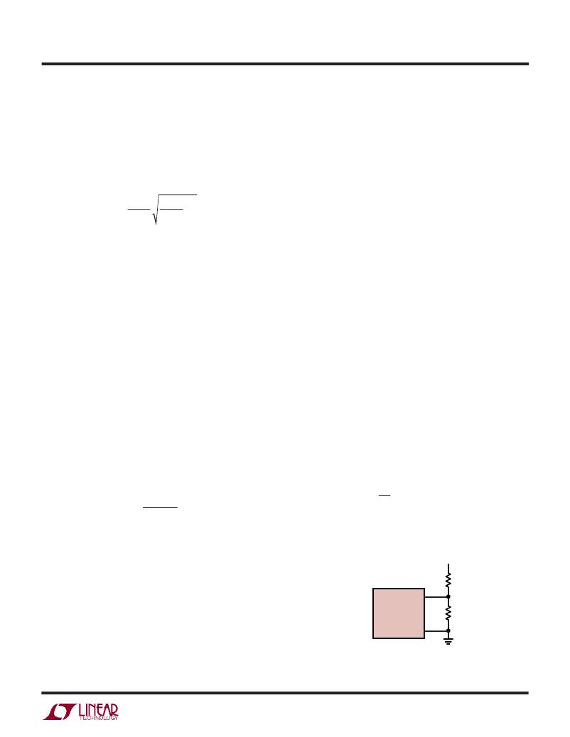
�Output� Voltage� Programming�
�The� output� voltage� is� set� by� an� external� resistive� divider�
�according� to� the� following� equation:�
�?� R� 2� ?�
�?� R� 1� ?�
�The� resistive� divider� allows� pin� V� FB� to� sense� a� fraction� of�
�the� output� voltage� as� shown� in� Figure� 2.�
�V� OUT�
�R2�
�V� FB�
�capacitors� offer� very� low� ESR� but� have� lower� capacitance�
�density� than� other� types.� Tantalum� capacitors� have� the�
�highest� capacitance� density� but� it� is� important� to� only� use�
�types� that� have� been� surge� tested� for� use� in� switching�
�LTC3414�
�SGND�
�R1�
�3414� F02�
�power� supplies.� Aluminum� electrolytic� capacitors� have�
�Figure� 2.� Setting� the� Output� Voltage�
�significantly� higher� ESR,� but� can� be� used� in� cost-sensitive�
�3414fb�
�9�
�相关PDF资料 |
PDF描述 |
|---|---|
| EBC40DRTI-S13 | CONN EDGECARD 80POS .100 EXTEND |
| LT1054IS8#PBF | IC REG SWITCHD CAP DBL INV 8SOIC |
| LT1766IGN#PBF | IC REG BUCK ADJ 1.5A 16SSOP |
| ESC20DREN-S13 | CONN EDGECARD 40POS .100 EXTEND |
| LT3508HFE#PBF | IC REG BUCK ADJ 1.4A DL 16TSSOP |
相关代理商/技术参数 |
参数描述 |
|---|---|
| LTC3414IFE | 制造商:Linear Technology 功能描述:Conv DC-DC Single Step Down 2.25V to 5.5V 20-Pin TSSOP EP |
| LTC3414IFE N57875 | 制造商: 功能描述: 制造商:undefined 功能描述: |
| LTC3414IFE#PBF | 功能描述:IC REG BUCK SYNC ADJ 4A 20TSSOP RoHS:是 类别:集成电路 (IC) >> PMIC - 稳压器 - DC DC 开关稳压器 系列:- 标准包装:250 系列:- 类型:降压(降压) 输出类型:固定 输出数:1 输出电压:1.2V 输入电压:2.05 V ~ 6 V PWM 型:电压模式 频率 - 开关:2MHz 电流 - 输出:500mA 同步整流器:是 工作温度:-40°C ~ 85°C 安装类型:表面贴装 封装/外壳:6-UFDFN 包装:带卷 (TR) 供应商设备封装:6-SON(1.45x1) 产品目录页面:1032 (CN2011-ZH PDF) 其它名称:296-25628-2 |
| LTC3414IFE#PBF | 制造商:Linear Technology 功能描述:IC SYNC STEP-DOWN REGULATOR 20-TSSOP 制造商:Linear Technology 功能描述:IC, SYNC STEP-DOWN REGULATOR, 20-TSSOP |
| LTC3414IFE#TR | 制造商:Linear Technology 功能描述:DP-SWREG/Monolithic, 4MHz, 4A Synch Step-dwn Regulator I Grade |
发布紧急采购,3分钟左右您将得到回复。