- 您现在的位置:买卖IC网 > PDF目录39425 > LTC3604IUD#TRPBF (LINEAR TECHNOLOGY CORP) SWITCHING REGULATOR, PQCC16 PDF资料下载
参数资料
| 型号: | LTC3604IUD#TRPBF |
| 厂商: | LINEAR TECHNOLOGY CORP |
| 元件分类: | 稳压器 |
| 英文描述: | SWITCHING REGULATOR, PQCC16 |
| 封装: | 3 X 3 MM, LEAD FREE, PLASTIC, MO-220WEED-2, QFN-16 |
| 文件页数: | 2/24页 |
| 文件大小: | 277K |
| 代理商: | LTC3604IUD#TRPBF |
LTC3604
10
3604f
APPLICATIONS INFORMATION
A general LTC3604 application circuit is shown on the rst
page of this data sheet. External component selection is
largely driven by the load requirement and begins with the
selection of the inductor L. Once the inductor is chosen, the
input capacitor, CIN, the output capacitor, COUT, the internal
regulatorcapacitor,CINTVCC,andtheboostcapacitor,CBOOST,
can be selected. Next, the feedback resistors are selected to
set the desired output voltage. Finally, the remaining option-
al external components can be selected for functions such
as external loop compensation, track/soft-start, externally
programmed oscillator frequency and PGOOD.
Operating Frequency
Selection of the operating frequency is a trade-off between
efciency and component size. High frequency operation
allows the use of smaller inductor and capacitor values.
Operation at lower frequencies improves efciency by
reducing internal gate charge losses but requires larger
inductance values and/or capacitance to maintain low
output ripple voltage.
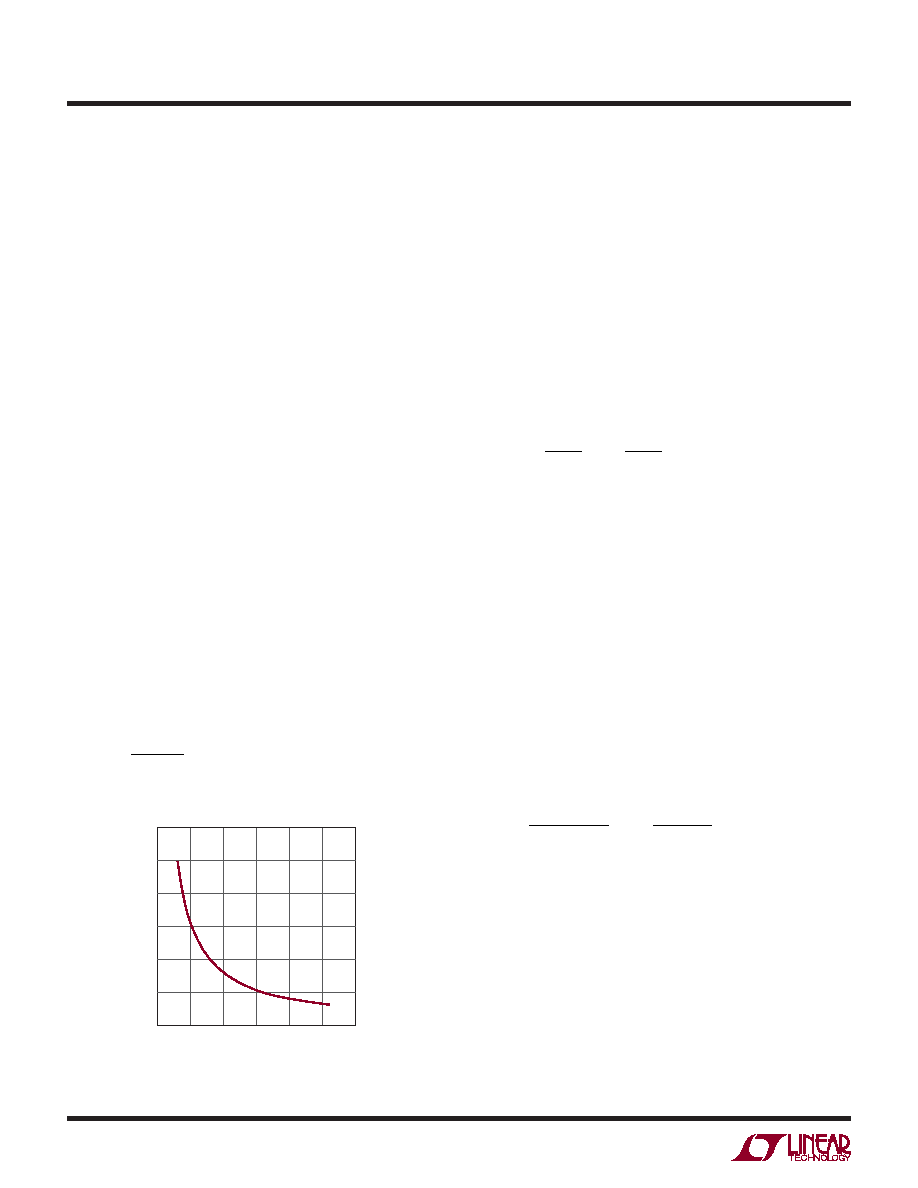
The operating frequency, fO, of the LTC3604 is determined
by an external resistor that is connected between the RT
pin and ground. The value of the resistor sets the ramp
current that is used to charge and discharge an internal
timing capacitor within the oscillator and can be calculated
by using the following equation:
R
E
f
RT
O
=
32 11
.
where RRT is in Ω and fO is in Hz.
Connecting the RT pin to INTVCC will default the converter
to fO = 2MHz; however, this switching frequency will be
more sensitive to process and temperature variations than
when using a resistor on RT (see Typical Performance
Characteristics).
Inductor Selection
For a given input and output voltage, the inductor value and
operating frequency determine the inductor ripple current.
More specically, the inductor ripple current decreases
with higher inductor value or higher operating frequency
according to the following equation:
ΔI
V
fL
V
L
OUT
IN
=
–
1
where
ΔIL=inductorripplecurrent,f=operatingfrequency
and L = inductor value. A trade-off between component
size, efciency and operating frequency can be seen from
this equation. Accepting larger values of
ΔIL allows the
use of lower value inductors but results in greater core
loss in the inductor, greater ESR loss in the output capaci-
tor, and larger output ripple. Generally, highest efciency
operation is obtained at low operating frequency with
small ripple current.
A reasonable starting point for setting the ripple current is
about 40% of IOUT(MAX). Note that the largest ripple current
occurs at the highest VIN. To guarantee the ripple current
does not exceed a specied maximum the inductance
should be chosen according to:
L
V
fI
V
OUT
LMAX
OUT
IN MAX
=
–
()
Δ
1
Once the value for L is known the type of inductor must
be selected. Actual core loss is independent of core size
for a xed inductor value but is very dependent on the
inductance selected. As the inductance increases, core loss
decreases. Unfortunately, increased inductance requires
more turns of wire leading to increased copper loss.
Ferrite designs exhibit very low core loss and are pre-
ferred at high switching frequencies, so design goals can
concentrate on copper loss and preventing saturation.
Ferrite core materials saturate “hard,” meaning the induc-
tance collapses abruptly when the peak design current is
RT (kΩ)
0
FREQUENCY
(kHz)
1000
2000
3000
4000
6000
100
200
300
400
3604 F01
500
600
5000
Figure 1. Switching Frequency vs RT
相关PDF资料 |
PDF描述 |
|---|---|
| LTC3604IUD#PBF | SWITCHING REGULATOR, PQCC16 |
| LTC3604EMSE#PBF | SWITCHING REGULATOR, PDSO16 |
| LTC3604EMSE#TRPBF | SWITCHING REGULATOR, PDSO16 |
| LTC3604IMSE#TRPBF | SWITCHING REGULATOR, PDSO16 |
| LTC3775EMSE#TRPBF | SWITCHING CONTROLLER, 575 kHz SWITCHING FREQ-MAX, PDSO16 |
相关代理商/技术参数 |
参数描述 |
|---|---|
| LTC3605AEUF#PBF | 功能描述:IC REG BUCK SYNC ADJ 5A 24QFN RoHS:是 类别:集成电路 (IC) >> PMIC - 稳压器 - DC DC 开关稳压器 系列:- 设计资源:Design Support Tool 标准包装:1 系列:- 类型:升压(升压) 输出类型:固定 输出数:1 输出电压:3V 输入电压:0.75 V ~ 2 V PWM 型:- 频率 - 开关:- 电流 - 输出:100mA 同步整流器:是 工作温度:-40°C ~ 85°C 安装类型:表面贴装 封装/外壳:SOT-23-5 细型,TSOT-23-5 包装:剪切带 (CT) 供应商设备封装:TSOT-23-5 其它名称:AS1323-BTTT-30CT |
| LTC3605AEUF#TRPBF | 功能描述:IC REG BUCK SYNC ADJ 5A 24QFN RoHS:是 类别:集成电路 (IC) >> PMIC - 稳压器 - DC DC 开关稳压器 系列:- 设计资源:Design Support Tool 标准包装:1 系列:- 类型:升压(升压) 输出类型:固定 输出数:1 输出电压:3V 输入电压:0.75 V ~ 2 V PWM 型:- 频率 - 开关:- 电流 - 输出:100mA 同步整流器:是 工作温度:-40°C ~ 85°C 安装类型:表面贴装 封装/外壳:SOT-23-5 细型,TSOT-23-5 包装:剪切带 (CT) 供应商设备封装:TSOT-23-5 其它名称:AS1323-BTTT-30CT |
| LTC3605AIUF#PBF | 功能描述:IC REG BUCK SYNC ADJ 5A 24QFN RoHS:是 类别:集成电路 (IC) >> PMIC - 稳压器 - DC DC 开关稳压器 系列:- 设计资源:Design Support Tool 标准包装:1 系列:- 类型:升压(升压) 输出类型:固定 输出数:1 输出电压:3V 输入电压:0.75 V ~ 2 V PWM 型:- 频率 - 开关:- 电流 - 输出:100mA 同步整流器:是 工作温度:-40°C ~ 85°C 安装类型:表面贴装 封装/外壳:SOT-23-5 细型,TSOT-23-5 包装:剪切带 (CT) 供应商设备封装:TSOT-23-5 其它名称:AS1323-BTTT-30CT |
| LTC3605AIUF#TRPBF | 功能描述:IC REG BUCK SYNC ADJ 5A 24QFN RoHS:是 类别:集成电路 (IC) >> PMIC - 稳压器 - DC DC 开关稳压器 系列:- 设计资源:Design Support Tool 标准包装:1 系列:- 类型:升压(升压) 输出类型:固定 输出数:1 输出电压:3V 输入电压:0.75 V ~ 2 V PWM 型:- 频率 - 开关:- 电流 - 输出:100mA 同步整流器:是 工作温度:-40°C ~ 85°C 安装类型:表面贴装 封装/外壳:SOT-23-5 细型,TSOT-23-5 包装:剪切带 (CT) 供应商设备封装:TSOT-23-5 其它名称:AS1323-BTTT-30CT |
| LTC3605EUF#PBF | 功能描述:IC REG BUCK SYNC ADJ 5A 24QFN RoHS:是 类别:集成电路 (IC) >> PMIC - 稳压器 - DC DC 开关稳压器 系列:- 标准包装:250 系列:- 类型:降压(降压) 输出类型:固定 输出数:1 输出电压:1.2V 输入电压:2.05 V ~ 6 V PWM 型:电压模式 频率 - 开关:2MHz 电流 - 输出:500mA 同步整流器:是 工作温度:-40°C ~ 85°C 安装类型:表面贴装 封装/外壳:6-UFDFN 包装:带卷 (TR) 供应商设备封装:6-SON(1.45x1) 产品目录页面:1032 (CN2011-ZH PDF) 其它名称:296-25628-2 |
发布紧急采购,3分钟左右您将得到回复。