- 您现在的位置:买卖IC网 > PDF目录15338 > LTC3704IMS#PBF (Linear Technology)IC REG CTRLR INV PWM CM 10-MSOP PDF资料下载
参数资料
| 型号: | LTC3704IMS#PBF |
| 厂商: | Linear Technology |
| 文件页数: | 19/28页 |
| 文件大小: | 0K |
| 描述: | IC REG CTRLR INV PWM CM 10-MSOP |
| 标准包装: | 50 |
| PWM 型: | 电流模式 |
| 输出数: | 1 |
| 频率 - 最大: | 1MHz |
| 占空比: | 97% |
| 电源电压: | 2.5 V ~ 36 V |
| 降压: | 无 |
| 升压: | 无 |
| 回扫: | 无 |
| 反相: | 是 |
| 倍增器: | 无 |
| 除法器: | 无 |
| Cuk: | 无 |
| 隔离: | 无 |
| 工作温度: | -40°C ~ 125°C |
| 封装/外壳: | 10-TFSOP,10-MSOP(0.118",3.00mm 宽) |
| 包装: | 管件 |
第1页第2页第3页第4页第5页第6页第7页第8页第9页第10页第11页第12页第13页第14页第15页第16页第17页第18页当前第19页第20页第21页第22页第23页第24页第25页第26页第27页第28页
�� �
�
�LTC3704�
�APPLICATIO� S� I� FOR� ATIO�
�Aluminum� electrolytic� and� dry� tantalum� capacitors� are�
�both� available� in� surface� mount� packages.� In� the� case� of�
�tantalum,� it� is� critical� that� the� capacitors� have� been� surge�
�tested� for� use� in� switching� power� supplies.� An� excellent�
�choice� is� AVX� TPS� series� of� surface� mount� tantalum.� Also,�
�ceramic� capacitors� are� now� available� with� extremely� low�
�ESR,� ESL� and� high� ripple� current� ratings.�
�Input� Capacitor� Selection�
�The� input� voltage� source� impedance� determines� the� size� of�
�the� input� capacitor,� which� is� typically� in� the� range� of� 10� μ� F�
�to� 100� μ� F.� A� low� ESR� capacitor� is� recommended,� although�
�it� is� not� as� critical� as� for� the� output� capacitor.�
�The� RMS� input� capacitor� ripple� current� for� a� positive-to-�
�negative� converter� is:�
�causes� the� inductor� current� to� quickly� decay� to� zero.�
�However,� because� Δ� I� L� is� small,� it� takes� multiple� cycles� for�
�the� current� to� ramp� back� up� to� I� BURST(PEAK)� .� During� this�
�inductor� charging� interval,� the� output� capacitor� must�
�supply� the� load� current� and� a� significant� droop� in� the�
�output� voltage� can� occur.� Generally,� it� is� a� good� idea� to�
�choose� a� value� of� inductor� Δ� I� L� between� 20%� and� 40%� of�
�I� IN(MAX)� .� The� alternative� is� to� either� increase� the� value� of�
�the� output� capacitor� or� disable� Burst� Mode� operation�
�using� the� MODE/SYNC� pin.�
�Burst� Mode� operation� can� be� defeated� by� connecting� the�
�MODE/SYNC� pin� to� a� high� logic-level� voltage� (either� with�
�a� control� input� or� by� connecting� this� pin� to� INTV� CC� ).� In� this�
�mode,� the� burst� clamp� is� removed,� and� the� chip� can�
�operate� at� constant� frequency� from� continuous� conduc-�
�tion� mode� (CCM)� at� full� load,� down� into� deep� discontinu-�
�I� RMS� (� CIN� )� =�
�1�
�12�
�?�
�V� IN(MIN)�
�L� 1� ?� f�
�?� D� MAX�
�ous� conduction� mode� (DCM)� at� light� load.� Prior� to� skip-�
�ping� pulses� at� very� light� load� (i.e.,� <� 5-10%� of� full� load),� the�
�Please� note� that� the� input� capacitor� can� see� a� very� high�
�surge� current� when� a� battery� is� suddenly� connected� to� the�
�input� of� the� converter� and� solid� tantalum� capacitors� can�
�fail� catastrophically� under� these� conditions.� Be� sure� to�
�specify� surge-tested� capacitors!�
�Burst� Mode� Operation� and� Considerations�
�The� choice� of� MOSFET� R� DS(ON)� and� inductor� value� also�
�determines� the� load� current� at� which� the� LTC3704� enters�
�Burst� Mode� operation.� When� bursting,� the� controller� clamps�
�the� peak� inductor� current� to� approximately:�
�controller� will� operate� with� a� minimum� switch� on-time� in�
�DCM.� Pulse� skipping� prevents� a� loss� of� control� of� the�
�output� at� very� light� loads� and� reduces� output� voltage�
�ripple.�
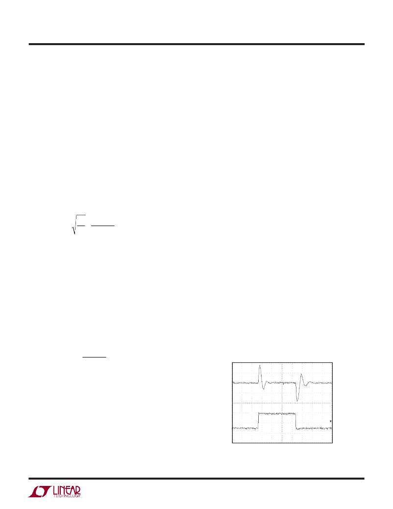
�Checking� Transient� Response�
�The� regulator� loop� response� can� be� verified� by� looking� at�
�the� load� transient� response.� Switching� regulators� gener-�
�ally� take� several� cycles� to� respond� to� an� instantaneous�
�step� in� resistive� load� current.� When� the� load� step� occurs,�
�V� O� immediately� shifts� by� an� amount� equal� to� (� Δ� I� LOAD� )(ESR),�
�and� then� C� O� begins� to� charge� or� discharge� (depending� on�
�I� BURST� (� PEAK� )� =�
�30� mV�
�R� DS� (� ON� )�
�the� direction� of� the� load� step)� as� shown� in� Figure� 14.� The�
�which� represents� about� 20%� of� the� maximum� 150mV�
�SENSE� pin� voltage.� The� corresponding� average� current�
�depends� upon� the� amount� of� ripple� current.� Lower� induc-�
�tor� values� (higher� Δ� I� L� )� will� reduce� the� load� current� at� which�
�V� OUT� (AC)�
�100mV/DIV�
�Burst� Mode� operations� begins,� since� it� is� the� peak� current�
�that� is� being� clamped.�
�I� OUT� (DC)�
�1A/DIV�
�2A�
�0.5A�
�The� output� voltage� ripple� can� increase� during� Burst� Mode�
�operation� if� Δ� I� L� is� substantially� less� than� I� BURST� .� This� can�
�occur� if� the� input� voltage� is� very� low� or� if� a� very� large�
�V� IN� =� 5V�
�V� OUT� =� –5V�
�250� μ� s/DIV�
�3704� F14�
�inductor� is� chosen.� At� high� duty� cycles,� a� skipped� cycle�
�Figure� 14.� Load� Step� Response� for� the� Circuit� in� Figure� 1.�
�3704fb�
�19�
�相关PDF资料 |
PDF描述 |
|---|---|
| LTC3851IGN#TRPBF | IC REG CTRLR BUCK PWM CM 16-SSOP |
| VI-2W1-EW-F2 | CONVERTER MOD DC/DC 12V 100W |
| EBA43DTAH | CONN EDGECARD 86POS R/A .125 SLD |
| EBA43DTAD | CONN EDGECARD 86POS R/A .125 SLD |
| VE-JWP-EW-F4 | CONVERTER MOD DC/DC 13.8V 100W |
相关代理商/技术参数 |
参数描述 |
|---|---|
| LTC3705EGN#PBF | 功能描述:IC CTRLR OCP 16SSOP RoHS:是 类别:集成电路 (IC) >> PMIC - AC-DC 转换器,离线开关 系列:- 标准包装:3,000 系列:- 输出隔离:隔离 频率范围:61kHz ~ 71kHz 输入电压:9.4 V ~ 28 V 输出电压:12V 功率(瓦特):- 工作温度:-40°C ~ 125°C 封装/外壳:SC-74,SOT-457 供应商设备封装:6-TSOP 包装:带卷 (TR) |
| LTC3705EGN#TRPBF | 功能描述:IC CTRLR OCP 16SSOP RoHS:是 类别:集成电路 (IC) >> PMIC - AC-DC 转换器,离线开关 系列:- 标准包装:3,000 系列:- 输出隔离:隔离 频率范围:61kHz ~ 71kHz 输入电压:9.4 V ~ 28 V 输出电压:12V 功率(瓦特):- 工作温度:-40°C ~ 125°C 封装/外壳:SC-74,SOT-457 供应商设备封装:6-TSOP 包装:带卷 (TR) |
| LTC3705IGN | 制造商:Linear Technology 功能描述:Forward Controller and Gate Driver 16-Pin SSOP N |
| LTC3705IGN#PBF | 功能描述:IC CTRLR OCP 16SSOP RoHS:是 类别:集成电路 (IC) >> PMIC - AC-DC 转换器,离线开关 系列:- 标准包装:3,000 系列:- 输出隔离:隔离 频率范围:61kHz ~ 71kHz 输入电压:9.4 V ~ 28 V 输出电压:12V 功率(瓦特):- 工作温度:-40°C ~ 125°C 封装/外壳:SC-74,SOT-457 供应商设备封装:6-TSOP 包装:带卷 (TR) |
| LTC3705IGN#TRPBF | 功能描述:IC CTRLR OCP 16SSOP RoHS:是 类别:集成电路 (IC) >> PMIC - AC-DC 转换器,离线开关 系列:- 标准包装:3,000 系列:- 输出隔离:隔离 频率范围:61kHz ~ 71kHz 输入电压:9.4 V ~ 28 V 输出电压:12V 功率(瓦特):- 工作温度:-40°C ~ 125°C 封装/外壳:SC-74,SOT-457 供应商设备封装:6-TSOP 包装:带卷 (TR) |
发布紧急采购,3分钟左右您将得到回复。