- 您现在的位置:买卖IC网 > PDF目录4962 > LTC3853EUJ#TRPBF (Linear Technology)IC REG CTRLR BUCK PWM CM 40-QFN PDF资料下载
参数资料
| 型号: | LTC3853EUJ#TRPBF |
| 厂商: | Linear Technology |
| 文件页数: | 13/36页 |
| 文件大小: | 0K |
| 描述: | IC REG CTRLR BUCK PWM CM 40-QFN |
| 产品培训模块: | LTC3853 Multiphase Switching Controller |
| 标准包装: | 2,000 |
| 系列: | PolyPhase® |
| PWM 型: | 电流模式 |
| 输出数: | 3 |
| 频率 - 最大: | 830kHz |
| 占空比: | 98% |
| 电源电压: | 4.5 V ~ 24 V |
| 降压: | 是 |
| 升压: | 无 |
| 回扫: | 无 |
| 反相: | 无 |
| 倍增器: | 无 |
| 除法器: | 无 |
| Cuk: | 无 |
| 隔离: | 无 |
| 工作温度: | -40°C ~ 125°C |
| 封装/外壳: | 40-WFQFN 裸露焊盘 |
| 包装: | 带卷 (TR) |
第1页第2页第3页第4页第5页第6页第7页第8页第9页第10页第11页第12页当前第13页第14页第15页第16页第17页第18页第19页第20页第21页第22页第23页第24页第25页第26页第27页第28页第29页第30页第31页第32页第33页第34页第35页第36页
�� ��
��
��LTC3853�
�OPERATION�
�Triple� vs� Dual� (2� +� 1)� Operation�
�The� LTC3853� can� be� used� to� regulate� three� different� outputs.�
�It� can� also� be� used� as� a� dual� output� controller� with� a� high�
�current� 2-phase� output� and� a� single� phase� output.� Tying�
�V� FB2� to� V� IN� through� a� 200k� resistor� switches� the� controller�
�from� triple� to� dual� (2� +� 1)� operation.� Do� not� exceed� the�
�absolute� maximum� current� rating� for� the� V� FB2� pin.�
�In� dual� (2� +� 1)� mode,� phase� 1� and� phase� 2� are� 180� degrees�
�apart� (instead� of� 120� degrees)� with� phase� 3� remaining� at�
�APPLICATIONS� INFORMATION�
�The� Typical� Application� on� the� first� page� is� a� basic� LTC3853�
�application� circuit.� LTC3853� can� be� configured� to� use� either�
�DCR� (inductor� resistance)� sensing� or� low� value� resistor�
�sensing.� The� choice� between� the� two� current� sensing�
�schemes� is� largely� a� design� tradeoff� between� cost,� power�
�consumption,� and� accuracy.� DCR� sensing� is� becoming�
�popular� because� it� saves� expensive� current� sensing� resis-�
�tors� and� is� more� power� efficient,� especially� in� high� current�
�applications.� However,� current� sensing� resistors� provide�
�the� most� accurate� current� limits� for� the� controller.� Other�
�external� component� selection� is� driven� by� the� load� require-�
�ment,� and� begins� with� the� selection� of� R� SENSE� (if� R� SENSE� is�
�used)� and� inductor� value.� Next,� the� power� MOSFETs� are� se-�
�lected.� Finally,� input� and� output� capacitors� are� selected.�
�Current� Limit� Programming�
�The� I� LIM� pin� is� a� tri-level� logic� input� which� sets� the� maxi-�
�mum� current� limit� of� the� controller.� When� I� LIM� is� either�
�grounded,� floated� or� tied� to� INTV� CC� ,� the� typical� value� for�
�the� maximum� current� sense� threshold� will� be� 30mV,� 50mV�
�or� 75mV,� respectively.�
�Which� setting� should� be� used?� For� the� best� current� limit�
�accuracy,� use� the� 75mV� setting.� The� 30mV� setting� will� allow�
�for� the� use� of� very� low� DCR� inductors� or� sense� resistors,�
�but� at� the� expense� of� current� limit� accuracy.� The� 50mV�
�setting� is� a� good� balance� between� the� two.� For� single� output�
�dual� phase� applications� ((2� +� 1)� mode),� use� the� 50mV� or�
�75mV� setting� for� optimal� current� sharing.�
�240� degrees� from� phase� 1.� The� I� TH1� and� I� TH2� pins� must� be�
�shorted� together� externally� and� so� must� the� TK/SS1� and�
�TK/SS2� pins� for� proper� operating� of� the� 2� phase� portion�
�of� the� controller.� RUN2� should� be� grounded.� RUN1� will�
�now� control� both� phases� 1� and� 2,� while� RUN3� continues�
�to� control� the� turn� on� of� phase� 3.�
�Phase� 3� is� also� capable� of� regulating� up� to� a� 13.5V� output�
�in� either� mode,� while� phases� 1� and� 2� are� limited� to� a� 5.3V�
�output.�
�SENSE� +� and� SENSE� –� Pins�
�The� SENSE� +� and� SENSE� –� pins� are� the� inputs� to� the� current�
�comparators.� The� common� mode� input� voltage� range� of�
�the� current� comparators� is� 0V� to� 5.3V� for� phases� 1� and�
�2,� and� 0V� to� 13.5V� for� phase� 3.� Both� SENSE� pins� are� high�
�impedance� inputs� with� small� base� currents� of� less� than�
�1μA.� When� the� SENSE� pins� ramp� up� from� 0V� to� 1.4V,� the�
�small� base� currents� flow� out� of� the� SENSE� pins.� When�
�the� SENSE� pins� ramp� down� from� the� maximum� common�
�mode� voltage� to� 1.1V,� the� small� base� currents� flow� into�
�the� SENSE� pins.� The� high� impedance� inputs� to� the� cur-�
�rent� comparators� allow� accurate� DCR� sensing.� However,�
�care� must� be� taken� not� to� float� these� pins� during� normal�
�operation.�
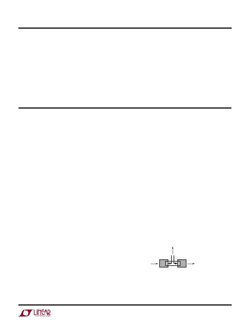
�Filter� components� mutual� to� the� sense� lines� should� be�
�placed� close� to� the� LTC3853,� and� the� sense� lines� should�
�run� close� together� to� a� Kelvin� connection� underneath� the�
�current� sense� element� (shown� in� Figure� 1).� Sensing� cur-�
�rent� elsewhere� can� effectively� add� parasitic� inductance�
�and� capacitance� to� the� current� sense� element,� degrading�
�TO� SENSE� FILTER,�
�NEXT� TO� THE� CONTROLLER�
�C� OUT�
�INDUCTOR� OR� R� SENSE� 3853� F01�
�Figure� 1.� Sense� Lines� Placement� with� Inductor� or� Sense� Resistor�
�3853fa�
�13�
�相关PDF资料 |
PDF描述 |
|---|---|
| LT1619ES8#PBF | IC REG CTRLR PWM CM 8-SOIC |
| ABC13DRXI-S734 | CONN EDGECARD 26POS DIP .100 SLD |
| ABC17DRTH-S734 | CONN EDGECARD 34POS DIP .100 SLD |
| LTC3851EUD#PBF | IC REG CTRLR BUCK PWM CM 16-QFN |
| RCA24DTAD | CONN EDGECARD 48POS R/A .125 SLD |
相关代理商/技术参数 |
参数描述 |
|---|---|
| LTC3853IUJ#PBF | 功能描述:IC REG CTRLR BUCK PWM CM 40-QFN RoHS:是 类别:集成电路 (IC) >> PMIC - 稳压器 - DC DC 切换控制器 系列:PolyPhase® 标准包装:4,500 系列:PowerWise® PWM 型:控制器 输出数:1 频率 - 最大:1MHz 占空比:95% 电源电压:2.8 V ~ 5.5 V 降压:是 升压:无 回扫:无 反相:无 倍增器:无 除法器:无 Cuk:无 隔离:无 工作温度:-40°C ~ 125°C 封装/外壳:6-WDFN 裸露焊盘 包装:带卷 (TR) 配用:LM1771EVAL-ND - BOARD EVALUATION LM1771 其它名称:LM1771SSDX |
| LTC3853IUJ#TRPBF | 功能描述:IC REG CTRLR BUCK PWM CM 40-QFN RoHS:是 类别:集成电路 (IC) >> PMIC - 稳压器 - DC DC 切换控制器 系列:PolyPhase® 标准包装:4,500 系列:PowerWise® PWM 型:控制器 输出数:1 频率 - 最大:1MHz 占空比:95% 电源电压:2.8 V ~ 5.5 V 降压:是 升压:无 回扫:无 反相:无 倍增器:无 除法器:无 Cuk:无 隔离:无 工作温度:-40°C ~ 125°C 封装/外壳:6-WDFN 裸露焊盘 包装:带卷 (TR) 配用:LM1771EVAL-ND - BOARD EVALUATION LM1771 其它名称:LM1771SSDX |
| LTC3854EDDB#PBF | 制造商:Linear Technology 功能描述:DP-SWREG/Controller, Cut Tape Small Footprint, Low Pin Count Synchronous Step-Do |
| LTC3854EDDB#TRMPBF | 功能描述:IC REG CTRLR BUCK PWM CM 12-DFN RoHS:是 类别:集成电路 (IC) >> PMIC - 稳压器 - DC DC 切换控制器 系列:- 标准包装:2,500 系列:- PWM 型:电流模式 输出数:1 频率 - 最大:500kHz 占空比:96% 电源电压:4 V ~ 36 V 降压:无 升压:是 回扫:无 反相:无 倍增器:无 除法器:无 Cuk:无 隔离:无 工作温度:-40°C ~ 125°C 封装/外壳:24-WQFN 裸露焊盘 包装:带卷 (TR) |
| LTC3854EDDB#TRPBF | 功能描述:IC REG CTRLR BUCK PWM CM 12-DFN RoHS:是 类别:集成电路 (IC) >> PMIC - 稳压器 - DC DC 切换控制器 系列:- 标准包装:2,500 系列:- PWM 型:电流模式 输出数:1 频率 - 最大:500kHz 占空比:96% 电源电压:4 V ~ 36 V 降压:无 升压:是 回扫:无 反相:无 倍增器:无 除法器:无 Cuk:无 隔离:无 工作温度:-40°C ~ 125°C 封装/外壳:24-WQFN 裸露焊盘 包装:带卷 (TR) |
发布紧急采购,3分钟左右您将得到回复。