- 您现在的位置:买卖IC网 > PDF目录16301 > LTC4010CFE#PBF (Linear Technology)IC CHARGER NIMH/NICD 16-TSSOP PDF资料下载
参数资料
| 型号: | LTC4010CFE#PBF |
| 厂商: | Linear Technology |
| 文件页数: | 15/24页 |
| 文件大小: | 0K |
| 描述: | IC CHARGER NIMH/NICD 16-TSSOP |
| 标准包装: | 95 |
| 功能: | 充电管理 |
| 电池化学: | 镍镉(NiCd)、镍金属氢化物(NiMH) |
| 电源电压: | 4.5 V ~ 34 V |
| 工作温度: | 0°C ~ 85°C |
| 安装类型: | 表面贴装 |
| 封装/外壳: | 16-TSSOP(0.173",4.40mm)裸露焊盘 |
| 供应商设备封装: | 16-TSSOP-EP |
| 包装: | 管件 |
�� �
�
�LTC4010�
�APPLICATIONS� INFORMATION�
�Table� 2.� LTC4010� Charging� Parameters�
�STATE�
�PC�
�FC�
�CHEM�
�PIN�
�Open�
�GND�
�BAT�
�CHEMISTRY�
�Both�
�NiCd�
�NiMH�
�TIMER�
�t� MAX� /12�
�t� MAX�
�t� MAX�
�T� MIN�
�5°C�
�5°C�
�5°C�
�T� MAX�
�45°C�
�60°C�
�60°C�
�I� CHRG�
�I� PROG� /5�
�I� PROG�
�I� PROG�
�TERMINATION� CONDITION�
�Timer� Expires�
�–20mV� per� Cell� or� 2°C/Minute�
�1.5°C/Minute� for� First� t� MAX� /12� Minutes� if� Initial�
�V� CELL� <� 1.325V�
�–10mV� per� Cell� or� 1°C/Minute� After� t� MAX� /12� Minutes�
�or� if� Initial� V� CELL� >� 1.325V�
�TOC�
�AR�
�GND�
�NiMH�
�Both�
�t� MAX� /3�
�5°C�
�5°C�
�60°C�
�45°C�
�I� PROG� /10� Timer� Expires�
�V� CELL� <� 1.325V�
�0�
�PC:�
�FC:�
�TOC:�
�AR:�
�Precharge�
�Fast� Charge� (Initial� –?V� Termination� Hold� Off� of� t� MAX� /12� Minutes� May� Apply)�
�Top-Off� Charge� (Only� for� NiMH� ?T/?t� FC� Termination� After� Initial� t� MAX� /12� Period)�
�Automatic� Recharge� (Temperature� Limits� Apply� to� State� Termination� Only)�
�Table� 3.� LTC4010� Time� Limit� Programming� Examples�
�R� TIMER�
�24.9k�
�33.2k�
�49.9k�
�66.5k�
�100k�
�TYPICAL� FAST�
�CHARGE� RATE�
�2C�
�1.5C�
�1C�
�0.75C�
�C/2�
�PRECHARGE� LIMIT�
�(MINUTES)�
�3.8�
�5�
�7.5�
�10�
�15�
�FAST� CHARGE�
�VOLTAGE� STABILIZATION�
�(MINUTES)�
�3.8�
�5�
�7.5�
�10�
�15�
�FAST� CHARGE� LIMIT�
�(HOURS)�
�0.75�
�1�
�1.5�
�2�
�3�
�TOP-OFF�
�CHARGE�
�(MINUTES)�
�15�
�20�
�30�
�40�
�60�
�(� ?� )�
�R� TIMER� =�
�+�
�V� CDIV�
�chargingstates.Tosomedegree,thevalueshouldreflect�
�how� closely� the� programmed� charge� current� matches� the�
�1C� rate� of� targeted� battery� packs.� The� maximum� fast� charge�
�period� is� determined� by� the� following� equation:�
�t� MAX� (Hours)�
�30� ?� 10� –� 6�
�Some� typical� timing� values� are� detailed� in� Table� 3.� R� TIMER�
�should� not� be� less� than� 15k.� The� actual� time� limits� used�
�by� the� LTC4010� have� a� resolution� of� approximately� ±� 30�
�seconds� in� addition� to� the� tolerances� given� the� Electrical�
�Characteristics� table.� If� the� timer� ends� without� a� valid�
�–?V� or� ?T/?t� charge� termination,� the� charger� enters� the�
�fault� state.� The� maximum� time� period� is� approximately�
�4.3� hours.�
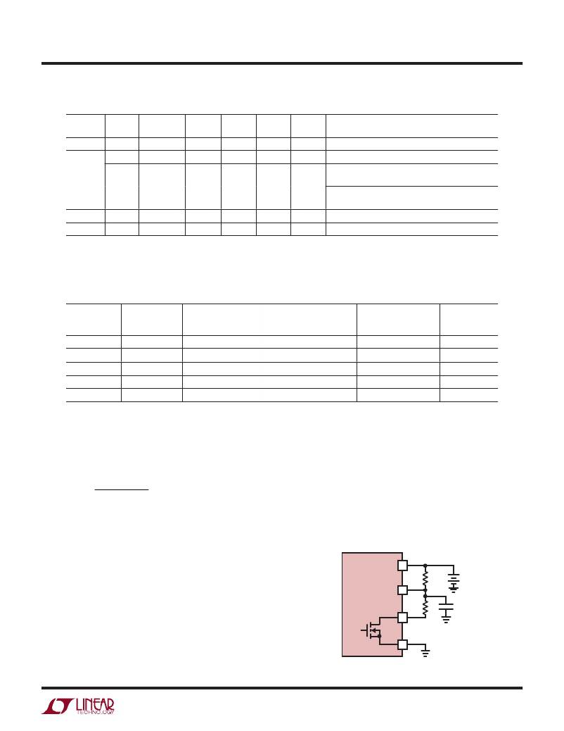
�Cell� Voltage� Network� Design�
�An� external� resistor� network� is� required� to� provide� the�
�average� single-cell� voltage� to� the� V� CELL� pin� of� the� LTC4010.�
�The� proper� circuit� for� multicell� packs� is� shown� in� Figure� 3.�
�The� ratio� of� R2� to� R1� should� be� a� factor� of� (n� –� 1),� where�
�n� is� the� number� of� series� cells� in� the� battery� pack.� The�
�value� of� R1� should� be� between� 1k� and� 100k.� This� range�
�limits� the� sensing� error� caused� by� V� CELL� leakage� current�
�and� prevents� the� ON� resistance� of� the� internal� NFET� be-�
�tween� V� CDIV� and� GND� from� causing� a� significant� error� in�
�the� V� CELL� voltage.� The� external� resistor� network� is� also�
�used� to� detect� battery� insertion� and� removal.� The� filter�
�FOR� TWO� OR�
�MORE� SERIES� CELLS�
�BAT� 10�
�LTC4010� R2�
�V� CELL� 6�
�R1� C1�
�7�
�R2� =� R1(n� –� 1)�
�GND�
�4�
�4010� F03�
�Figure� 3.� Multiple� Cell� Voltage� Divider�
�4010fb�
� �
�相关PDF资料 |
PDF描述 |
|---|---|
| EMC12DRTH | CONN EDGECARD 24POS .100 EXTEND |
| RBA18DRMN | CONN EDGECARD 36POS .125 SQ WW |
| ECC20DRAS | CONN EDGECARD 40POS R/A .100 SLD |
| ABC08DRXN | CONN EDGECARD 16POS .100 DIP SLD |
| ABC08DRXH | CONN EDGECARD 16POS .100 DIP SLD |
相关代理商/技术参数 |
参数描述 |
|---|---|
| LTC4010CFETR | 制造商:LINER 制造商全称:Linear Technology 功能描述:High Efficiency Standalone Nickel Battery Charger |
| LTC4010CFETRPBF | 制造商:LINER 制造商全称:Linear Technology 功能描述:High Efficiency Standalone Nickel Battery Charger |
| LTC4010EFE | 制造商:LINEAR 制造商全称:LINEAR 功能描述:High Efficiency Standalone Nickel Battery Charger |
| LTC4011 | 制造商:LINER 制造商全称:Linear Technology 功能描述:High Efficiency Standalone Nickel Battery Charger |
| LTC4011_1 | 制造商:LINER 制造商全称:Linear Technology 功能描述:High Efficiency Standalone Nickel Battery Charger |
发布紧急采购,3分钟左右您将得到回复。