- 您现在的位置:买卖IC网 > PDF目录69007 > LTC4065LEDC#PBF (LINEAR TECHNOLOGY CORP) 1-CHANNEL POWER SUPPLY SUPPORT CKT, PDSO6 PDF资料下载
参数资料
| 型号: | LTC4065LEDC#PBF |
| 厂商: | LINEAR TECHNOLOGY CORP |
| 元件分类: | 电源管理 |
| 英文描述: | 1-CHANNEL POWER SUPPLY SUPPORT CKT, PDSO6 |
| 封装: | 2 X 2 MM, 0.75 MM HEIGHT, LEAD FREE, EXPOSED PAD, PLASTIC, MO-229WCCD-2, DFN-6 |
| 文件页数: | 10/16页 |
| 文件大小: | 168K |
| 代理商: | LTC4065LEDC#PBF |
3
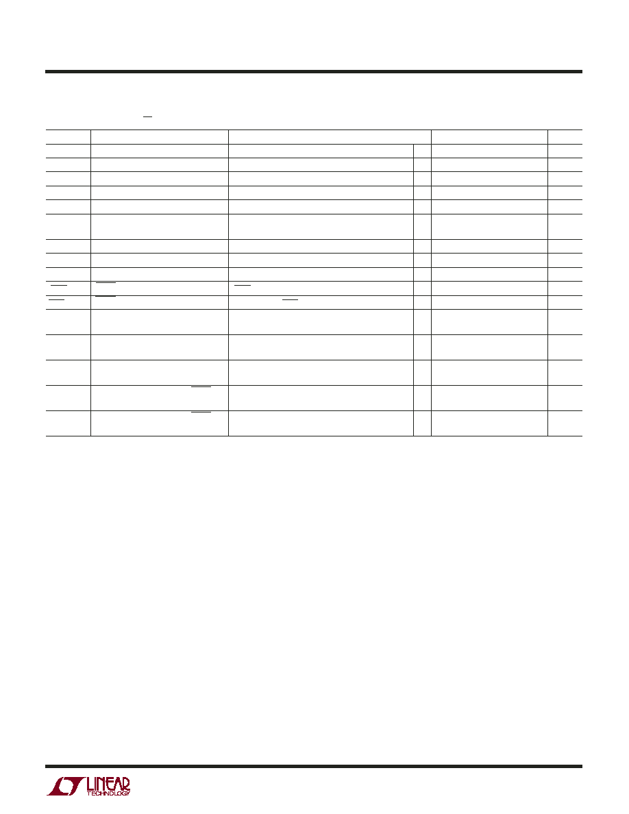
LTC4065L/LTC4065LX
4065lxfa
SYMBOL
PARAMETER
CONDITIONS
MIN
TYP
MAX
UNITS
tSS
Soft-Start Time
170
s
ITRKL
Trickle Charge Current
VBAT = 2V, RPROG = 1.33k (0.1%) (Note 7)
13
15.5
18
mA
VTRKL
Trickle Charge Threshold Voltage
VBAT Rising (Note 7)
●
2.7
2.9
3.05
V
VTRHYS
Trickle Charge Hysteresis Voltage
(Note 7)
90
mV
VRECHRG
Recharge Battery Threshold Voltage
VFLOAT – VRECHRG, 0°C < TA < 85°C
70
100
130
mV
VUVCL1
(VCC – VBAT) Undervoltage Current
IBAT = 90%, RPROG = 2k, Programmed Charge Current
150
190
300
mV
VUVCL2
Limit
IBAT = 10%, RPROG = 2k, Programmed Charge Current
80
125
150
mV
tTIMER
Termination Timer
●
3
4.5
6
Hrs
Recharge Time
●
1.5
2.25
3
Hrs
Low-Battery Trickle Charge Time
VBAT = 2.5V
●
0.75
1.125
1.5
Hrs
VCHRG
CHRG Pin Output Low Voltage
ICHRG = 5mA
●
60
105
mV
ICHRG
CHRG Pin Input Current
VBAT = 4.5V, VCHRG = 5V
●
01
A
IC/10
End of Charge Indication Current
RPROG = 1.33k (Note 5)
●
0.08
0.095
0.11
mA/mA
Level
TLIM
Junction Temperature in Constant
115
°C
Temperature Mode
RON
Power FET “ON” Resistance
IBAT = 150mA
1.5
(Between VCC and BAT)
fBADBAT
Defective Battery Detection CHRG
2
Hz
Pulse Frequency
DBADBAT
Defective Battery Detection CHRG
75
%
Pulse Frequency Duty Ratio
The
● denotes specifications which apply over the full operating temperature range, otherwise specifications are TA = 25°C.
VCC = 5V, VBAT = 3.8V, VEN = 0V unless otherwise specified. (Note 2)
ELECTRICAL CHARACTERISTICS
Note 1: Stresses beyond those listed under Absolute Maximum Ratings
may cause permanent damage to the device. Exposure to any Absolute
Maximum Rating condition for extended periods may affect device
reliability and lifetime.
Note 2: The LTC4065L is guaranteed to meet performance specifications
from 0
°C to 70°C. Specifications over the –40°C to 85°C operating
temperature range are assured by design, characterization and correlation
with statistical process controls.
Note 3: Failure to solder the exposed backside of the package to the PC
board ground plane will result in a thermal resistance much higher than
rated.
Note 4: Although the LTC4065L functions properly at 3.75V input, full
charge current requires an input voltage greater than the desired final
battery voltage per the
VUVCL1 specification.
Note 5: IC/10 is expressed as a fraction of measured full charge current
with indicated PROG resistor.
Note 6: This IC includes overtemperature protection that is intended to
protect the device during momentary overload conditions. Junction
temperature will exceed 125
°C when overtemperature protection is active.
Continuous operation above the specified maximum operating junction
temperature may impair device reliability.
Note 7: This parameter is not applicable to the LTC4065LX.
相关PDF资料 |
PDF描述 |
|---|---|
| LTC4065LXEDC#TRMPBF | 1-CHANNEL POWER SUPPLY SUPPORT CKT, PDSO6 |
| LTC4069EDC-4.4#TRMPBF | 1-CHANNEL POWER SUPPLY SUPPORT CKT, PDSO6 |
| LTC4088EDE-1#TR | 1-CHANNEL POWER SUPPLY SUPPORT CKT, PDSO14 |
| LTC4088EDE | 3 A BATTERY CHARGE CONTROLLER, 2.7 kHz SWITCHING FREQ-MAX, PDSO14 |
| LTC4096EDD#PBF | 1-CHANNEL POWER SUPPLY SUPPORT CKT, PDSO10 |
相关代理商/技术参数 |
参数描述 |
|---|---|
| LTC4065LX | 制造商:LINER 制造商全称:Linear Technology 功能描述:Standalone 250mA Li-Ion Battery Charger in 2 x 2 DFN |
| LTC4065LXEDC | 制造商:LINER 制造商全称:Linear Technology 功能描述:Standalone 750mA Li-Ion Battery Charger in 2 x 2 DFN |
| LTC4065LXEDC#PBF | 制造商:Linear Technology 功能描述:Battery Charger Li-Ion/Li-Pol 155mA 4.2V 6-Pin DFN EP T/R |
| LTC4065LXEDC#TRPBF | 功能描述:IC CHARGER LI-ION 6-DFN RoHS:是 类别:集成电路 (IC) >> PMIC - 电池管理 系列:- 标准包装:61 系列:- 功能:电源管理 电池化学:锂离子(Li-Ion)、锂聚合物(Li-Pol) 电源电压:4.35 V ~ 5.5 V 工作温度:-40°C ~ 85°C 安装类型:表面贴装 封装/外壳:22-WFDFN 裸露焊盘 供应商设备封装:22-DFN(6x3)裸露焊盘 包装:管件 |
| LTC4066 | 制造商:LINER 制造商全称:Linear Technology 功能描述:USB Power Controller and Li-Ion Linear Charger with Low Loss Ideal Diode |
发布紧急采购,3分钟左右您将得到回复。