参数资料
| 型号: | LTC4258CGW#TRPBF |
| 厂商: | Linear Technology |
| 文件页数: | 8/28页 |
| 文件大小: | 0K |
| 描述: | IC POE 802.3AF QUAD 36-SSOP |
| 标准包装: | 1,000 |
| 控制器类型: | 以太网供电控制器(POE) |
| 接口: | IEEE 802.3af |
| 电源电压: | 3 V ~ 4 V |
| 电流 - 电源: | 2.5mA |
| 工作温度: | 0°C ~ 70°C |
| 安装类型: | 表面贴装 |
| 封装/外壳: | 36-BSOP(0.295",7.50mm 宽) |
| 供应商设备封装: | 36-SSOP |
| 包装: | 带卷 (TR) |
第1页第2页第3页第4页第5页第6页第7页当前第8页第9页第10页第11页第12页第13页第14页第15页第16页第17页第18页第19页第20页第21页第22页第23页第24页第25页第26页第27页第28页
LTC4258
16
4258fb
measures the port voltage through the DETECT
n pin. Note
that class 4 is presently specified by the IEEE as reserved
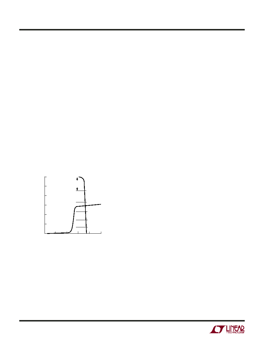
for future use. Figure 13 shows a PD load line, starting with
the shallow slope of the 25k signature resistor below 10V,
then drawing the classification current (in this case, class 3)
between 14.5V and 20.5V. The LTC4258’s load line for clas-
sification is also shown in Figure 13. It has low impedance
until current limit is reached at 55mA (min).
The LTC4258 will classify a port immediately after a
successful detection cycle in Semiauto or Auto modes, or
when commanded to in Manual mode. It measures the PD
classification signature current by applying 18V (typ) to
the port and measuring the resulting current. It reports the
detected class in the Class Status bits in the correspond-
ing Port Status register. Note that in Auto mode, the port
will power up regardless of which class is detected.
The classification circuitry is disabled when the port is in
Shutdown mode, powered up, or the corresponding Class
Enable bit is cleared.
Gate Currents
Once the decision has been made to turn on power to a
port, the LTC4258 uses a 50
A current source to pull up
on the GATE pin. Under normal power-up circumstances,
the MOSFET gate will charge up rapidly to VT (the MOSFET
threshold voltage), the MOSFET current will rise quickly to
the current limit level and the GATE pin will be servoed to
maintain the proper IINRUSH charging current. When out-
put charging is complete, the MOSFET current will fall and
the GATE pin will be allowed to continue rising to fully
enhance the MOSFET and minimize its on resistance. The
final VGS is nominally 13V. When a port is turned off, a
50
A current source pulls down on the GATE pin, turning
the MOSFET off in a controlled manner.
No External Capacitors
No external capacitors are required on the GATE pins for
active current limit stability, lowering part count and cost.
This also allows the fastest possible turn-off under severe
overcurrent conditions, providing maximum safety and
protection for the MOSFETs, load devices and board traces.
Connecting capacitors to the external MOSFET gates can
adversely affect the LTC4258’s ability to respond to a
shorted port.
Inrush Control
The 802.3af standard lists two separate maximum current
limits, ILIM and IINRUSH. Because they have identical val-
ues, the LTC4258 implements both as a single current
limit using VLIM (described below). Their functions are
differentiated through the use of tICUT and tSTART, respec-
tively (see tICUT Timing and tSTART Timing sections). To
maintain consistency with the standard, the IINRUSH term
is used when referring to an initial tSTART power-up event.
When the LTC4258 turns on a port, it turns on the MOSFET
by pulling up on the gate. The LTC4258 is designed to
power up the port in current limit, limiting the inrush
current to IINRUSH.
The port voltage will quickly rise to the point where the PD
reaches its input turn-on threshold and begins to draw
current to charge its bypass capacitance, slowing the rate
of port voltage increase.
APPLICATIO S I FOR ATIO
WU
UU
Figure 13. PD Classification
VOLTAGE (VCLASS)
0
CURRENT
(mA)
60
50
40
30
20
10
0
510
15
20
4258 F13
25
TYPICAL
CLASS 3
PD LOAD
LINE
48mA
33mA
PSE LOAD LINE
23mA
14.5mA
6.5mA
CLASS 4
CLASS 2
CLASS 1
CLASS 0
CLASS 3
OVER
CURRENT
POWER CONTROL
The primary function of the LTC4258 is to control the
delivery of power to the PSE port. It does this by control-
ling the gate drive voltage of an external power MOSFET
while monitoring the current via a sense resistor and the
output voltage at the OUT pin. This circuitry serves to
couple the raw isolated –48V input supply to the port in a
controlled manner that satisfies the PD’s power needs
while minimizing disturbances on the –48V backplane.
相关PDF资料 |
PDF描述 |
|---|---|
| LTC4259ACGW#TR | IC CTRLR POE QUAD AC DISC 36SSOP |
| LTC4264IDE#TRPBF | IC CNTRLR PD INTERFACE 12-DFN |
| LTC4266IGW#PBF | IC CTRLR IEEE 802.3AT 36-SSOP |
| LTC4267IDHC#TRPBF | IC POE 802.3AF INTERFACE 16-DFN |
| LTC4278IDKD#TRPBF | IC PD IEEE 802.3AT 25.5W 32-DFN |
相关代理商/技术参数 |
参数描述 |
|---|---|
| LTC4259A | 制造商:LINER 制造商全称:Linear Technology 功能描述:Power over Ethernet IEEE 802.3af PD Interface with Integrated Switching Regulator |
| LTC4259A-1 | 制造商:LINER 制造商全称:Linear Technology 功能描述:Synchronous No-Opto Flyback Controller |
| LTC4259ACGW | 功能描述:IC CTRLR POE QUAD AC DISC 36SSOP RoHS:否 类别:集成电路 (IC) >> 接口 - 控制器 系列:- 标准包装:2,450 系列:- 控制器类型:SPI 总线至 I²C 总线桥接 接口:I²C,串行,SPI 电源电压:2.4 V ~ 3.6 V 电流 - 电源:11mA 工作温度:-40°C ~ 85°C 安装类型:表面贴装 封装/外壳:24-VFQFN 裸露焊盘 供应商设备封装:24-HVQFN(4x4) 包装:托盘 配用:568-3511-ND - DEMO BOARD SPI TO I2C 其它名称:935286452157SC18IS600IBSSC18IS600IBS-ND |
| LTC4259ACGW#PBF | 功能描述:IC CTRLR POE QUAD AC DISC 36SSOP RoHS:是 类别:集成电路 (IC) >> 接口 - 控制器 系列:- 标准包装:2,450 系列:- 控制器类型:SPI 总线至 I²C 总线桥接 接口:I²C,串行,SPI 电源电压:2.4 V ~ 3.6 V 电流 - 电源:11mA 工作温度:-40°C ~ 85°C 安装类型:表面贴装 封装/外壳:24-VFQFN 裸露焊盘 供应商设备封装:24-HVQFN(4x4) 包装:托盘 配用:568-3511-ND - DEMO BOARD SPI TO I2C 其它名称:935286452157SC18IS600IBSSC18IS600IBS-ND |
| LTC4259ACGW#TR | 功能描述:IC CTRLR POE QUAD AC DISC 36SSOP RoHS:否 类别:集成电路 (IC) >> 接口 - 控制器 系列:- 标准包装:2,450 系列:- 控制器类型:SPI 总线至 I²C 总线桥接 接口:I²C,串行,SPI 电源电压:2.4 V ~ 3.6 V 电流 - 电源:11mA 工作温度:-40°C ~ 85°C 安装类型:表面贴装 封装/外壳:24-VFQFN 裸露焊盘 供应商设备封装:24-HVQFN(4x4) 包装:托盘 配用:568-3511-ND - DEMO BOARD SPI TO I2C 其它名称:935286452157SC18IS600IBSSC18IS600IBS-ND |
发布紧急采购,3分钟左右您将得到回复。