- 您现在的位置:买卖IC网 > PDF目录44997 > LTC4412IHVS6#TRM (LINEAR TECHNOLOGY CORP) 1-CHANNEL POWER SUPPLY SUPPORT CKT, PDSO6 PDF资料下载
参数资料
| 型号: | LTC4412IHVS6#TRM |
| 厂商: | LINEAR TECHNOLOGY CORP |
| 元件分类: | 电源管理 |
| 英文描述: | 1-CHANNEL POWER SUPPLY SUPPORT CKT, PDSO6 |
| 封装: | PLASTIC, MO-193, TSOT-23, 6 PIN |
| 文件页数: | 12/12页 |
| 文件大小: | 176K |
| 代理商: | LTC4412IHVS6#TRM |
9
LTC4412HV
4412hvf
Automatic PowerPath Control
The applications shown in Figures 1, 2 and 3 are automatic
ideal diode controllers that require no assistance from a
microcontroller. Each of these will automatically connect
the higher supply voltage, after accounting for certain
diode forward voltage drops, to the load with application
of the higher supply voltage.
Figure 1 illustrates an application circuit for automatic
switchover of a load between a battery and a wall adapter
or other power input. With application of the battery, the
load will initially be pulled up by the drain-source diode of
the P-channel MOSFET. As the LTC4412HV comes into
action, it will control the MOSFET’s gate to turn it on and
reduce the MOSFET’s voltage drop from a diode drop to
20mV. The system is now in the low loss forward regula-
tion mode. Should the wall adapter input be applied, the
Schottky diode will pull up the SENSE pin, connected to the
load, above the battery voltage and the LTC4412HV will
turn the MOSFET off. The STAT pin will then sink current
indicating an auxiliary input is connected. The battery is
now supplying no load current and all the load current
flows through the Schottky diode. A silicon diode could be
used instead of the Schottky, but will result in higher
power dissipation and heating due to the higher forward
voltage drop.
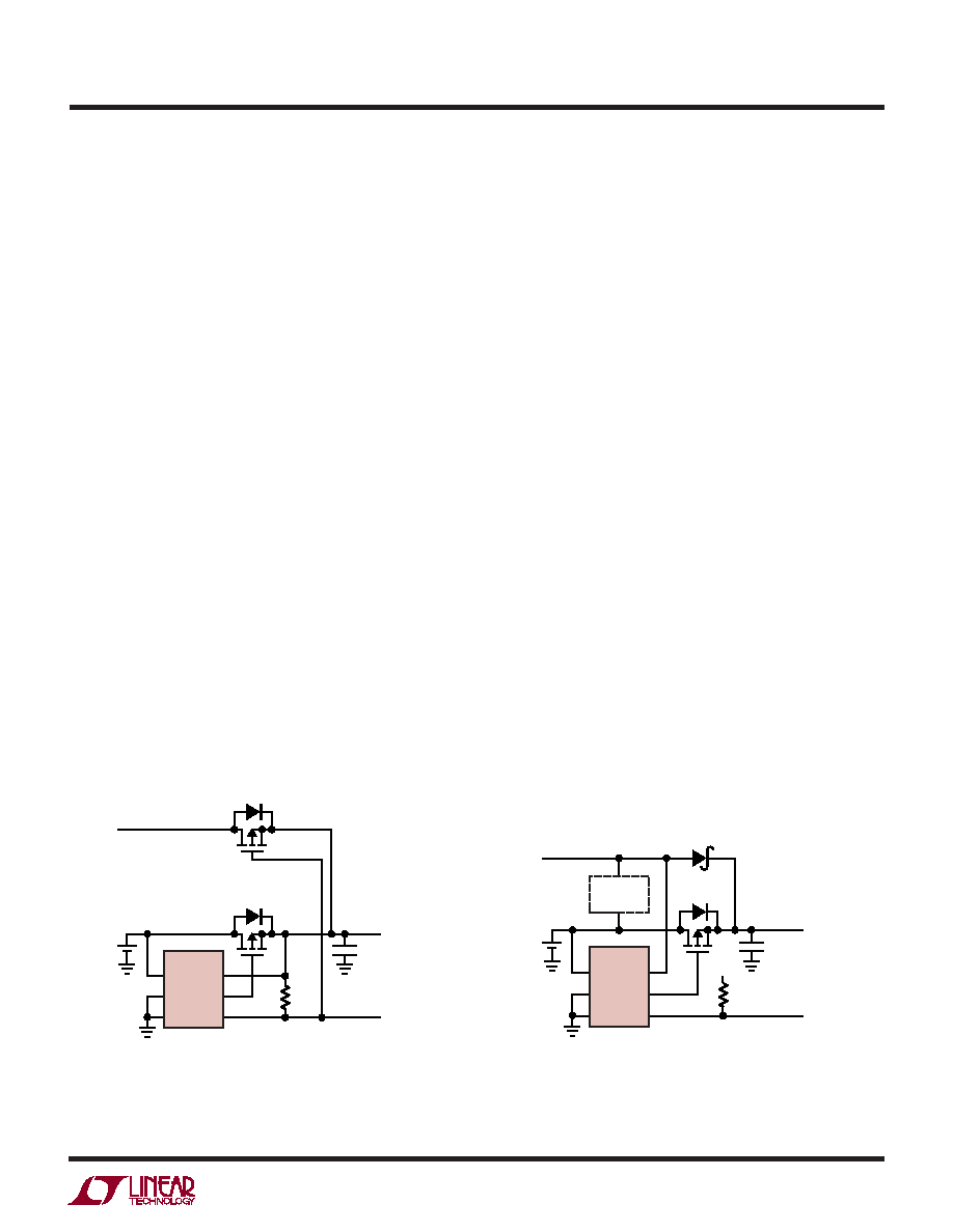
Figure 2 illustrates an application circuit for automatic
switchover of load between a battery and a wall adapter
that features lowest power loss. Operation is similar to
Figure 1 except that an auxiliary P-channel MOSFET
replaces the diode. The STAT pin is used to turn on the
MOSFET once the SENSE pin voltage exceeds the battery
voltage by 20mV. When the wall adapter input is applied,
the drain-source diode of the auxiliary MOSFET will turn
on first to pull up the SENSE pin and turn off the primary
MOSFET followed by turning on of the auxiliary MOSFET.
Once the auxiliary MOSFET has turned on the voltage drop
across it can be very low depending on the MOSFET’s
characteristics.
Figure 3 illustrates an application circuit for the automatic
switchover of a load between a battery and a wall adapter
in the comparator mode. It also shows how a battery
charger can be connected. This circuit differs from Figure
1 in the way the SENSE pin is connected. The SENSE pin
is connected directly to the auxiliary power input and not
the load. This change forces the LTC4412HV’s control
circuitry to operate in an open-loop comparator mode.
While the battery supplies the system, the GATE pin
voltage will be forced to its lowest clamped potential,
instead of being regulated to maintain a 20mV drop across
the MOSFET. This has the advantages of minimizing
power loss in the MOSFET by minimizing its RON and not
having the influence of a linear control loop’s dynamics. A
possible disadvantage is if the auxiliary input ramps up
slow enough the load voltage will initially droop before
TYPICAL APPLICATIO S
U
VIN
GND
CTL
SENSE
GATE
STAT
1
2
3
6
5
4
LTC4412HV
PRIMARY
P-CHANNEL
MOSFET
COUT
TO LOAD
STATUS OUTPUT
DROPS WHEN A
WALL ADAPTER
IS PRESENT
470k
4412HV F02
BATTERY
CELL(S)
WALL
ADAPTER
INPUT
*
AUXILIARY
P-CHANNEL
MOSFET
*DRAIN-SOURCE DIODE OF MOSFET
Figure 2. Automatic Switchover of Load Between a Battery and a
Wall Adapter with Auxiliary P-Channel MOSFET for Lowest Loss
VIN
GND
CTL
SENSE
GATE
STAT
1
2
3
6
5
4
LTC4412HV
BATTERY
CHARGER
P-CHANNEL
MOSFET
COUT
TO LOAD
STATUS OUTPUT
IS LOW WHEN A
WALL ADAPTER
IS PRESENT
470k
*DRAIN-SOURCE DIODE OF MOSFET
4412HV F03
VCC
BATTERY
CELL(S)
*
WALL
ADAPTER
INPUT
Figure 3. Automatic Switchover of Load Between
a Battery and a Wall Adapter in Comparator Mode
相关PDF资料 |
PDF描述 |
|---|---|
| LTC4412IHVS6#TR | 1-CHANNEL POWER SUPPLY SUPPORT CKT, PDSO6 |
| LTC4412IHVS6#PBF | 1-CHANNEL POWER SUPPLY SUPPORT CKT, PDSO6 |
| LTC4413EDD-2 | SPECIALTY ANALOG CIRCUIT, PDSO10 |
| LTC4413EDD-1#TR | SPECIALTY ANALOG CIRCUIT, PDSO10 |
| LTC4413EDD2#TR | SPECIALTY ANALOG CIRCUIT, PDSO10 |
相关代理商/技术参数 |
参数描述 |
|---|---|
| LTC4412IS6#PBF | 制造商:Linear Technology 功能描述:Bulk 制造商:Linear Technology 功能描述:IC POWERPATH CONTROLLER SOT-23-6 制造商:Linear Technology 功能描述:IC, POWERPATH CONTROLLER, SOT-23-6 制造商:Linear Technology 功能描述:IC, POWERPATH CONTROLLER, SOT-23-6; Input Voltage:28V; Output Current:50A; Output Voltage:36V; Supply Voltage Min:2.5V; Supply Voltage Max:28V; No. of Pins:6; No. of Outputs:1; Operating Temperature Min:-40C ;RoHS Compliant: Yes |
| LTC4412IS6#TRMPBF | 功能描述:IC PWR PATH CNTRLR TSOT23-6 RoHS:是 类别:集成电路 (IC) >> PMIC - O 圈控制器 系列:PowerPath™ 标准包装:1,000 系列:- 应用:电池备份,工业/汽车,大电流开关 FET 型:- 输出数:5 内部开关:是 延迟时间 - 开启:100ns 延迟时间 - 关闭:- 电源电压:3 V ~ 5.5 V 电流 - 电源:250µA 工作温度:0°C ~ 70°C 安装类型:表面贴装 封装/外壳:16-SOIC(0.154",3.90mm 宽) 供应商设备封装:16-SOIC N 包装:带卷 (TR) |
| LTC4412IS6#TRPBF | 功能描述:IC CTRL LOWLOSS PWRPATH TSOT23-6 RoHS:是 类别:集成电路 (IC) >> PMIC - O 圈控制器 系列:PowerPath™ 标准包装:1,000 系列:- 应用:电池备份,工业/汽车,大电流开关 FET 型:- 输出数:5 内部开关:是 延迟时间 - 开启:100ns 延迟时间 - 关闭:- 电源电压:3 V ~ 5.5 V 电流 - 电源:250µA 工作温度:0°C ~ 70°C 安装类型:表面贴装 封装/外壳:16-SOIC(0.154",3.90mm 宽) 供应商设备封装:16-SOIC N 包装:带卷 (TR) |
| LTC4412IS6TRMPBF | 制造商:Linear Technology 功能描述:PowerPath Controller Low-Loss TSOT23-6 |
| LTC4413EDD | 制造商:Linear Technology 功能描述:Dual Ideal Diodes 10-Pin DFN EP |
发布紧急采购,3分钟左右您将得到回复。