- 您现在的位置:买卖IC网 > Datasheet目录868 > LTM4600HVIV#PBF (Linear Technology)IC DC/DC UMODULE 10A 104-LGA Datasheet资料下载
参数资料
| 型号: | LTM4600HVIV#PBF |
| 厂商: | Linear Technology |
| 文件页数: | 17/24页 |
| 文件大小: | 0K |
| 描述: | IC DC/DC UMODULE 10A 104-LGA |
| 产品培训模块: | Power Module vs. Discrete DC to DC |
| 软件下载: | LTM4600HV Spice Model |
| 产品目录绘图: | LTM Series_15x15x2.8 |
| 设计资源: | DC823B-B Design Files LTM4600HVIV#PBF Footprint.bxl |
| 特色产品: | μModule Products |
| 标准包装: | 119 |
| 系列: | µModule® |
| 类型: | 非隔离(POL) |
| 输出数: | 1 |
| 电压 - 输入(最小): | 4.5V |
| 电压 - 输入(最大): | 28V |
| Voltage - Output 1: | 0.6 ~ 5 V |
| 电流 - 输出(最大): | 10A |
| 安装类型: | 表面贴装 |
| 封装/外壳: | 104-LGA |
| 尺寸/尺寸: | 0.59" L x 0.59" W x 0.11" H(15.0mm x 15.0mm x 2.8mm) |
| 包装: | 托盘 |
| 工作温度: | -40°C ~ 85°C |
| 效率: | 92% |
| 产品目录页面: | 2711 (CN2011-ZH PDF) |
| 配用: | DC823B-B-ND - BOARD EVAL LTM4600HV |
�� �
�
�LTM4600HV�
�APPLICATIO� S� I� FOR� ATIO�
�(DC)� DUTY� CYCLE� =� ON�
�DC� =� =� OUT�
�V� IN�
�t�
�t� s�
�t� s� V� IN�
�t� ON� V�
�C� IN�
�t� OFF�
�t� ON�
�FREQ� =�
�DC�
�t� ON�
�4602� F25�
�PERIOD� t� s�
�PGND�
�The� LTM4600HV� has� a� minimum� (t� ON� )� on� time� of� 100�
�nanoseconds� and� a� minimum� (t� OFF� )� off� time� of� 400�
�nanoseconds.� The� 2.4V� clamp� on� the� ramp� threshold� as�
�LOAD�
�V� OUT�
�TOP� LAYER�
�4600hv� F20�
�a� function� of� V� OUT� will� cause� the� switching� frequency� to�
�increase� by� the� ratio� of� V� OUT� /2.4V� for� 3.3V� and� 5V� outputs.�
�This� is� due� to� the� fact� the� on� time� will� not� increase� as� V� OUT�
�increases� past� 2.4V.� Therefore,� if� the� nominal� switch-�
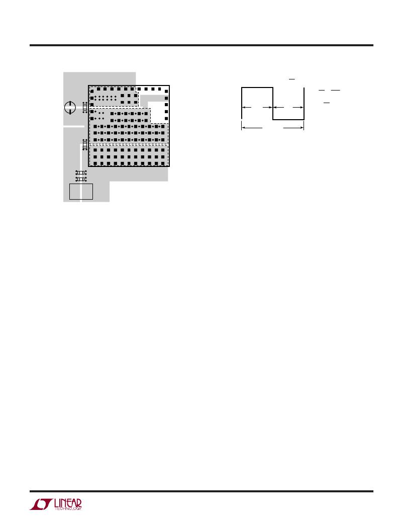
�Figure� 20.� Recommended� PCB� Layout�
�LTM4600HV� Frequency� Adjustment�
�The� LTM4600HV� is� designed� to� typically� operate� at� 850kHz�
�across� most� input� and� output� conditions.� The� control� ar-�
�chitecture� is� constant� on� time� valley� mode� current� control.�
�The� f� ADJ� pin� is� typically� left� open� or� decoupled� with� an�
�optional� 1000pF� capacitor.� The� switching� frequency� has�
�been� optimized� to� maintain� constant� output� ripple� over� the�
�operating� conditions.� The� equations� for� setting� the� operat-�
�ing� frequency� are� set� around� a� programmable� constant� on�
�time.� This� on� time� is� developed� by� a� programmable� current�
�into� an� on� board� 10pF� capacitor� that� establishes� a� ramp�
�that� is� compared� to� a� voltage� threshold� equal� to� the� output�
�voltage� up� to� a� 2.4V� clamp.� This� I� ON� current� is� equal� to:�
�I� ON� =� (V� IN� –� 0.7V)/110k,� with� the� 110k� onboard� resistor�
�from� V� IN� to� f� ADJ� .� The� on� time� is� equal� to� t� ON� =� (V� OUT� /I� ON� )�
�?� 10pF� and� t� OFF� =� t� s� –� t� ON� .� The� frequency� is� equal� to:� Freq.�
�=� DC/t� ON� .� The� I� ON� current� is� proportional� to� V� IN� ,� and� the�
�regulator� duty� cycle� is� inversely� proportional� to� V� IN� ,� there-�
�fore� the� step-down� regulator� will� remain� relatively� constant�
�frequency� as� the� duty� cycle� adjustment� takes� place� with�
�lowering� V� IN� .� The� on� time� is� proportional� to� V� OUT� up� to� a�
�2.4V� clamp.� This� will� hold� frequency� relatively� constant�
�with� different� output� voltages� up� to� 2.4V.� The� regulator�
�switching� period� is� comprised� of� the� on� time� and� off� time�
�as� depicted� in� the� following� waveform.� The� on� time� is�
�equal� to� t� ON� =� (V� OUT� /I� ON� )� ?� 10pF� and� t� OFF� =� t� s� –� t� ON� .� The�
�frequency� is� equal� to:� Frequency� =� DC/t� ON� ).�
�ing� frequency� is� 850kHz,� then� the� switching� frequency�
�will� increase� to� ~1.2MHz� for� 3.3V,� and� ~1.7MHz� for� 5V�
�outputs� due� to� Frequency� =� (DC/t� ON� )� When� the� switching�
�frequency� increases� to� 1.2MHz,� then� the� time� period� t� S� is�
�reduced� to� ~833� nanoseconds� and� at� 1.7MHz� the� switching�
�period� reduces� to� ~588� nanoseconds.� When� higher� duty�
�cycle� conversions� like� 5V� to� 3.3V� and� 12V� to� 5V� need� to�
�be� accommodated,� then� the� switching� frequency� can� be�
�lowered� to� alleviate� the� violation� of� the� 400ns� minimum�
�off� time.� Since� the� total� switching� period� is� t� S� =� t� ON� +� t� OFF� ,�
�t� OFF� will� be� below� the� 400ns� minimum� off� time.� A� resistor�
�from� the� f� ADJ� pin� to� ground� can� shunt� current� away� from�
�the� on� time� generator,� thus� allowing� for� a� longer� on� time�
�and� a� lower� switching� frequency.� 12V� to� 5V� and� 5V� to�
�3.3V� derivations� are� explained� in� the� data� sheet� to� lower�
�switching� frequency� and� accommodate� these� step-down�
�conversions.�
�Equations� for� setting� frequency� for� 12V� to� 5V:�
�I� ON� =� (V� IN� –� 0.7V)/110k;� I� ON� =� 103μA�
�frequency� =� (I� ON� /[2.4V� ?� 10pF])� ?� DC� =� 1.79MHz;�
�DC� =� duty� cycle,� duty� cycle� is� (V� OUT� /V� IN� )�
�t� S� =� t� ON� +� t� OFF� ,� t� ON� =� on-time,� t� OFF� =� off-time� of� the�
�switching� period;� t� S� =� 1/frequency�
�t� OFF� must� be� greater� than� 400ns,� or� t� S� –� t� ON� >� 400ns.�
�t� ON� =� DC� ?� t� S�
�1MHz� frequency� or� 1μs� period� is� chosen� for� 12V� to� 5V.�
�4600hvfc�
�17�
�相关PDF资料 |
PDF描述 |
|---|---|
| LTM4600IV#PBF | IC DC/DC UMODULE 10A 104-LGA |
| LTM4601AHVEV#PBF | IC DC/DC UMODULE 12A 133-LGA |
| LTM4601AIY#PBF | IC DC/DC UMODULE 12A 133-BGA |
| LTM4602IV#PBF | IC DC/DC UMODULE 6A 104-LGA |
| LTM4603HVEV#PBF | IC DC/DC UMODULE 6A 118-LGA |
相关代理商/技术参数 |
参数描述 |
|---|---|
| LTM4600HVIV-TRPBF | 制造商:LINER 制造商全称:Linear Technology 功能描述:10A, 28VIN High Effi ciency DC/DC μModule |
| LTM4600HVMP | 制造商:LINER 制造商全称:Linear Technology 功能描述:Low VIN, 8A DC/DC Module Regulator with Tracking, Margining, and Frequency Synchronization |
| LTM4600HVMPV | 制造商:LINER 制造商全称:Linear Technology 功能描述:10A, 28VIN High Effi ciency DC/DC μModule |
| LTM4600HVMPV#PBF | 功能描述:IC DC/DC UMODULE 10A 104-LGA RoHS:是 类别:电源 - 板载 >> DC DC Converters 系列:µModule® 设计资源:Maxi/Mini/Micro Design Guide, Appl Manual 标准包装:1 系列:微型 类型:隔离 输出数:1 电压 - 输入(最小):18V 电压 - 输入(最大):36V Voltage - Output 1:48V Voltage - Output 2:- Voltage - Output 3:- 电流 - 输出(最大):* 电源(瓦) - 制造商系列:100W 电压 - 隔离:* 特点:* 安装类型:通孔 封装/外壳:模块 尺寸/尺寸:2.28" L x 1.45" W x 0.62" H(57.9mm x 36.8mm x 15.7mm) 包装:散装 工作温度:-20°C ~ 100°C 效率:* 电源(瓦特)- 最大:* 其它名称:1102-1290V24C48C100BL-ND |
| LTM4600HVMPV#PBF | 制造商:Linear Technology 功能描述:IC, STEP-DOWN DC/DC MODULE, LGA-104 |
发布紧急采购,3分钟左右您将得到回复。