- 您现在的位置:买卖IC网 > PDF目录67759 > LX1661CD-TR (MICROSEMI CORP-ANALOG MIXED SIGNAL GROUP) 1.5 A SWITCHING CONTROLLER, PDIP16 PDF资料下载
参数资料
| 型号: | LX1661CD-TR |
| 厂商: | MICROSEMI CORP-ANALOG MIXED SIGNAL GROUP |
| 元件分类: | 稳压器 |
| 英文描述: | 1.5 A SWITCHING CONTROLLER, PDIP16 |
| 封装: | LEAD FREE, PLASTIC, DIP-16 |
| 文件页数: | 3/15页 |
| 文件大小: | 376K |
| 代理商: | LX1661CD-TR |
A D V ANCED PWM C ONTROLLER
LX1660/1661
PRODUCT DA T ABOOK 1996/1997
11
Copyright 1998
Rev. 1.1a 10/25/2004
P RODUCTION D AT A S HEET
USING THE LX1660/61 DEVICES
INPUT CAPACITOR
The input capacitor and the input inductor are to filter the
pulsating current generated by the buck converter to reduce
interference to other circuits connected to the same 5V rail. In
addition, the input capacitor provides local de-coupling of the
buck converter. The capacitor should be rated to handle the RMS
current requirement. The RMS current is:
I
RMS = IL √ d(1-d)
where I
L is the inductor current and d is the duty cycle.
The
maximum value, when d = 50%, I
RMS = 0.5IL .
For 5V input and
output in the range of 2 to 3V, the required RMS current is very
close to 0.5I
L .
A high-frequency (ceramic) capacitor should be placed across
the drain of the top MOSFET and the source of the bottom one to
avoid ringing due to the parasitic inductor being switched ON and
OFF. See capacitor C
7 in the Product Highlight on the first page
of this data sheet.
TIMING CAPACITOR SELECTION
The frequency of operation of the LX1660 / 1661 is a function of
the duty cycle and OFF-time. The OFF-time is proportional to the
timing capacitor (connected to Pin 8, C
T ), and is modulated to
minimize frequency variations with duty cycle. The frequency is
constant, during steady-state operation, due to the modulation of
the OFF-time.
The timing capacitor (C
T) should be selected using the follow-
ing equation:
C
T =
where I
DIS is fixed at 200A and fS is the switching frequency
(recommended to be around 200kHz for optimal operation and
component selection).
When using a 5V input voltage, the switching frequency (f
S) can
be approximated as follows:
C
T = 0.621 *
Choosing a 680pF timing capacitor will result in an operating
frequency of 183kHz at V
OUT = 2.8V. When a 12V power input is
used, the capacitor value must be changed (the optimal timing
capacitor for 12V input will be in the range of 1000 - 1500pF).
CURRENT LIMIT
Current limiting occurs when a sensed voltage, proportional to
load current, exceeds the current-sense comparator threshold
value (90mV). The current can be sensed either by using a fixed
sense resistor in series with the inductor to cause a voltage drop
proportional to current, or by using a resistor and capacitor in
parallel with the inductor to sense the voltage drop across the
CURRENT LIMIT (continued)
parasitic resistance of the inductor. One should include an RC
filter at the CS+ and CS- inputs, as shown in the Application
Information section, to eliminate jitter and noise.
For most applications, the resistors R5, R6 can be set at 1k
,
and C1 can be in the 300-500pF range as a starting point. If a fine
trim or adjustment of the current trip level is required, C1 may be
shunted by a resistor. C1 will introduce a small delay into the
current limit trip point, which effectively raises the threshold.
Sense Resistor
The current sense resistor (R1) is selected according to the for-
mula:
R1 = V
TRIP / ITRIP
Where V
TRIP is the current sense comparator threshold (100mV)
and I
TRIP is the desired current limit. Typical choices are shown
below.
(1 - V
OUT / VIN ) * IDIS
f
S (1.52 - 0.29 * VOUT )
I
DIS
f
S
Load
Sense Resistor Value
Pentium-Class Processor (<10A)
5m
Pentium II Class (>10A)
2.5m
TABLE 2 - Current Sense Resistor Selection Guide
A smaller sense resistor will result in lower heat dissipation (IR)
and also a smaller output voltage droop at higher currents.
There are several alternative types of sense resistor. The sur-
face-mount metal “staple” form of resistor has the advantage of
exposure to free air to dissipate heat and its value can be con-
trolled very tightly. Its main drawback, however, is cost. An alter-
native is to construct the sense resistor using a copper PCB trace.
Although the resistance cannot be controlled as tightly, the PCB
trace is very low cost.
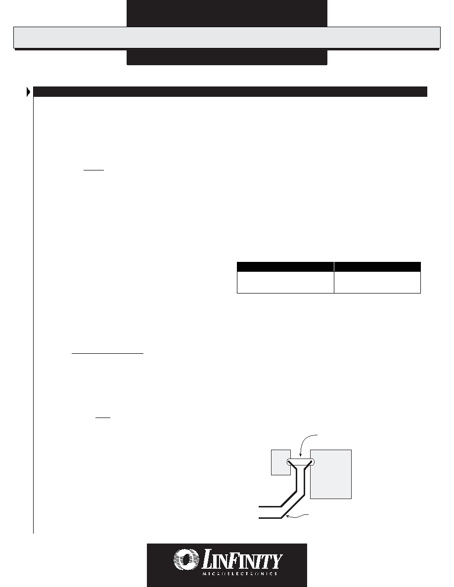
PCB Sense Resistor
A PCB sense resistor should be constructed as shown in Figure
7. By attaching directly to the large pads for the capacitor and
inductor, heat is dissipated efficiently by the larger copper masses.
Connect the current sense lines as shown to avoid any errors.
2.5m
Sense Resistor
100mil Wide, 850mil Long
2.5mm x 22mm (2 oz/ft2 copper)
Output
Capacitor Pad
Inductor
Sense Lines
FIGURE 7 — Sense Resistor Construction Diagram
相关PDF资料 |
PDF描述 |
|---|---|
| LX1660CD-TR | 1.5 A SWITCHING CONTROLLER, PDSO16 |
| LX1671-CPW | 1 A SWITCHING CONTROLLER, 345 kHz SWITCHING FREQ-MAX, PDSO38 |
| LX1671-CLQ | 1 A SWITCHING CONTROLLER, 345 kHz SWITCHING FREQ-MAX, PQCC38 |
| LX1671-CPWTR | 1 A SWITCHING CONTROLLER, 345 kHz SWITCHING FREQ-MAX, PDSO38 |
| LX1671-CLQTR | 1 A SWITCHING CONTROLLER, 345 kHz SWITCHING FREQ-MAX, PQCC38 |
相关代理商/技术参数 |
参数描述 |
|---|---|
| LX1661CN | 功能描述:IC PWM MONO SWITCHING REG 16DIP RoHS:是 类别:集成电路 (IC) >> PMIC - 稳压器 - 专用型 系列:- 产品培训模块:Lead (SnPb) Finish for COTS Obsolescence Mitigation Program 标准包装:2,000 系列:- 应用:电源,ICERA E400,E450 输入电压:4.1 V ~ 5.5 V 输出数:10 输出电压:可编程 工作温度:-40°C ~ 85°C 安装类型:表面贴装 封装/外壳:42-WFBGA,WLCSP 供应商设备封装:42-WLP 包装:带卷 (TR) |
| LX1662 | 制造商:MICROSEMI 制造商全称:Microsemi Corporation 功能描述:SINGLE-CHIP PROGRAMMABLE PWM CONTROLLERS WITH 5-BIT DAC |
| LX1662A | 制造商:MICROSEMI 制造商全称:Microsemi Corporation 功能描述:SINGLE-CHIP PROGRAMMABLE PWM CONTROLLERS WITH 5-BIT DAC |
| LX1662ACD | 功能描述:IC PWM PROG SGL 5BIT DAC 14SOIC RoHS:是 类别:集成电路 (IC) >> PMIC - 稳压器 - 专用型 系列:- 产品培训模块:Lead (SnPb) Finish for COTS Obsolescence Mitigation Program 标准包装:2,000 系列:- 应用:电源,ICERA E400,E450 输入电压:4.1 V ~ 5.5 V 输出数:10 输出电压:可编程 工作温度:-40°C ~ 85°C 安装类型:表面贴装 封装/外壳:42-WFBGA,WLCSP 供应商设备封装:42-WLP 包装:带卷 (TR) |
| LX1662ACN | 功能描述:IC PWM PROG SGL 5BIT DAC 14DIP RoHS:是 类别:集成电路 (IC) >> PMIC - 稳压器 - 专用型 系列:- 产品培训模块:Lead (SnPb) Finish for COTS Obsolescence Mitigation Program 标准包装:2,000 系列:- 应用:电源,ICERA E400,E450 输入电压:4.1 V ~ 5.5 V 输出数:10 输出电压:可编程 工作温度:-40°C ~ 85°C 安装类型:表面贴装 封装/外壳:42-WFBGA,WLCSP 供应商设备封装:42-WLP 包装:带卷 (TR) |
发布紧急采购,3分钟左右您将得到回复。