- 您现在的位置:买卖IC网 > PDF目录98004 > LX1677-CPWT (MICROSEMI CORP-ANALOG MIXED SIGNAL GROUP) 1.5 A SWITCHING CONTROLLER, 1100 kHz SWITCHING FREQ-MAX, PDSO38 PDF资料下载
参数资料
| 型号: | LX1677-CPWT |
| 厂商: | MICROSEMI CORP-ANALOG MIXED SIGNAL GROUP |
| 元件分类: | 稳压器 |
| 英文描述: | 1.5 A SWITCHING CONTROLLER, 1100 kHz SWITCHING FREQ-MAX, PDSO38 |
| 封装: | PLASTIC, TSSOP-38 |
| 文件页数: | 2/16页 |
| 文件大小: | 353K |
| 代理商: | LX1677-CPWT |
LX1677
PRELIMINARY DATA SHEET
Microsemi
Integrated Products Division
11861 Western Avenue, Garden Grove, CA. 92841, 714-898-8121, Fax: 714-893-2570
Page 10
WWW
.Microse
m
i
.CO
M
AMD64 Processor VRM Controller
I N T E GR A T ED
PRODUCT S
Copyright
2000
Rev 0.4a, 2003-03-03
TH EORY OF O PERATION (CONTINUED)
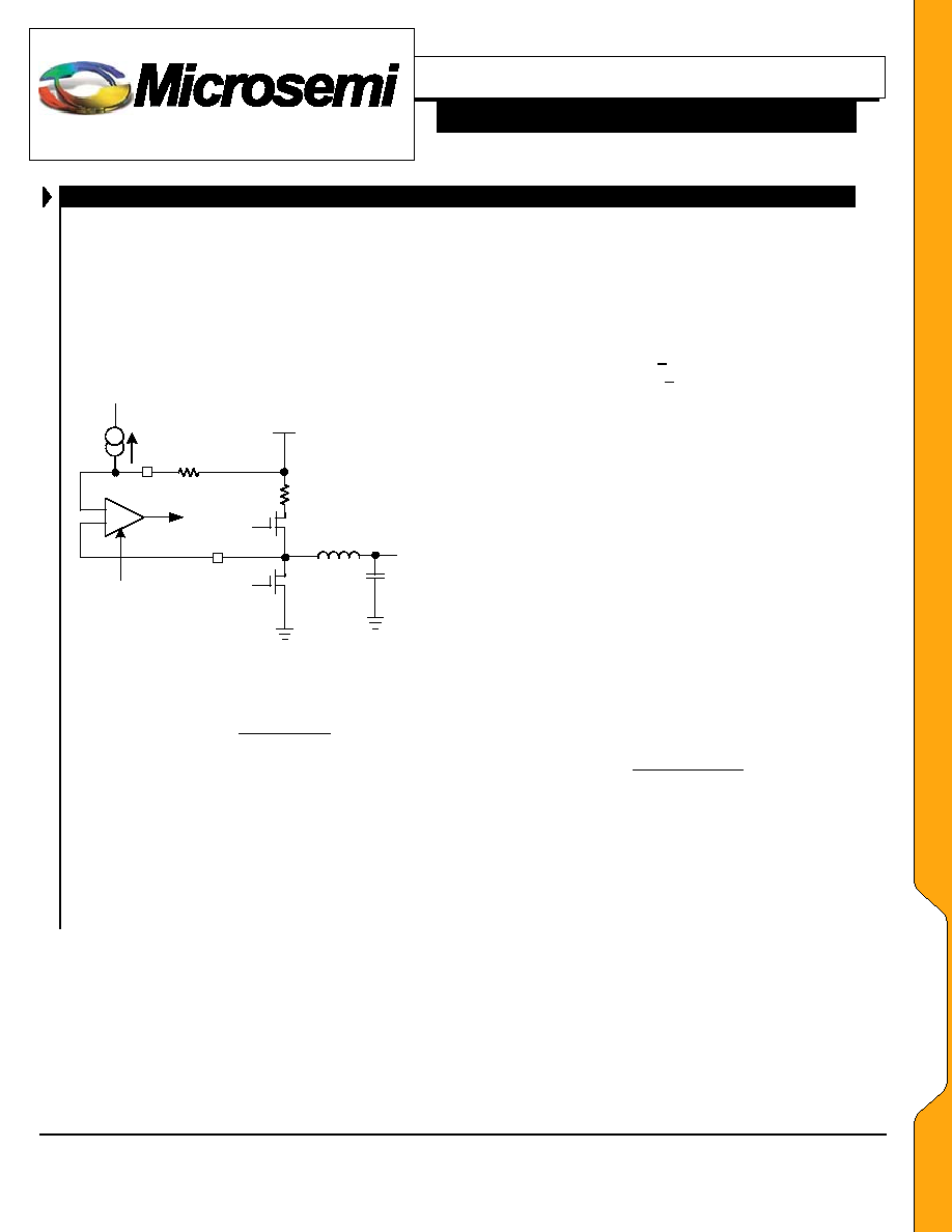
OVER-CURRENT PROTECTION (PHASE 3)
The hysteretic phase has its own current limit protection
because with it’s very fast response time with a 100 nH
inductor the upper MOSFET cannot be allowed to stay on
during an output short circuit condition. The phase 3 over-
current sensing uses the RDS(ON) of the upper MOSFET
with a resistor RSET to determine the over current limit
point. A current source draws 50uA through RSET which
determines the required drop across the MOSFET
RDS(ON) to initiate a current limit condition.
50 uA
+
_
RSET
Q2
+
_
Current Limit
Comparator
Q1
Vin
RDS(ON)
Vout
400nS Delay
ILIM3
VS3
Figure 4 –
Phase 3 Current Limit
Phase 3 RSET is calculated by:
uA
50
RDSon
ILimit
Rset
=
OVER VOLTAGE PROTECTION
An over voltage protection circuit monitors the output
voltage and will latch all three phases off if an over voltage
condition (greater than 2.35 V) is detected.
Both
MOSFETs for phase 3 will be held off and the lower
MOSFETs for phase 1 and 2 will be held on to discharge
the output capacitor till the output voltage drops below .85
volt, at .85 volts all MOSFETs will be turned off.
FAULT LOGIC
There are a number of possible states that will cause a
fault condition that will disable the output MOSFET
drivers. A fault condition will be caused by the following:
Enable (ENA) pin being pulled low
Over-current condition on either phase 1 or phase 3
Over Voltage output > 1.85V
Under Voltage output < 0.725V
In all cases except Over Voltage all MOSFET drivers
will be latched off. For an Over Voltage fault the lower
MOSFETs for phase 1 and 2 will be held on to discharge
the bulk capacitance on the output till a lower limit of
0.725 volts is reached then all MOSFETS will be turned
off.
To reset a fault it necessary to cycle the ENA pin low
then back high or remove and reapply the input voltage
VIN.
The Under Voltage monitor is not enabled until the
output voltage has ramped up to the level commanded by
the DACOUT pin and the PWGD output in high.
PWM FREQUENCY
An external resistor sets the PWM frequency from the
ROSC pin to ground.
The equation for ROSC is:
()
9
e
100
f
K
1
ROSC
+
=
where ROSC is in
, f is in Hz, K=105e-12
AA
PP
LL
IICC
AA
TT
IIOO
NN
SS
相关PDF资料 |
PDF描述 |
|---|---|
| LX1677-CLQT | 1.5 A SWITCHING CONTROLLER, 1100 kHz SWITCHING FREQ-MAX, PQCC38 |
| LX2203CLD-TR | 1-CHANNEL POWER SUPPLY SUPPORT CKT, PDSO10 |
| LX2203CLD-TR | 1-CHANNEL POWER SUPPLY SUPPORT CKT, PDSO10 |
| LX2207ILD-TR | 1-CHANNEL POWER SUPPLY SUPPORT CKT, PDSO12 |
| LY510ALHTR | SPECIALTY ANALOG CIRCUIT, PBGA16 |
相关代理商/技术参数 |
参数描述 |
|---|---|
| LX1681 | 制造商:MICROSEMI 制造商全称:Microsemi Corporation 功能描述:VOLTAGE - MODE PWM CONTROLLERS |
| LX1681_05 | 制造商:MICROSEMI 制造商全称:Microsemi Corporation 功能描述:Voltage-Mode PWM Controllers |
| LX1681CDM | 功能描述:IC REG CTRLR DIVIDER PWM 8-SOIC RoHS:是 类别:集成电路 (IC) >> PMIC - 稳压器 - DC DC 切换控制器 系列:- 标准包装:4,000 系列:- PWM 型:电压模式 输出数:1 频率 - 最大:1.5MHz 占空比:66.7% 电源电压:4.75 V ~ 5.25 V 降压:是 升压:无 回扫:无 反相:无 倍增器:无 除法器:无 Cuk:无 隔离:无 工作温度:-40°C ~ 85°C 封装/外壳:40-VFQFN 裸露焊盘 包装:带卷 (TR) |
| LX1681CDMT | 制造商:MICROSEMI 制造商全称:Microsemi Corporation 功能描述:Voltage-Mode SMPS Controller |
| LX1681CDM-TR | 制造商:MICROSEMI 制造商全称:Microsemi Corporation 功能描述:Voltage-Mode PWM Controllers |
发布紧急采购,3分钟左右您将得到回复。