- 您现在的位置:买卖IC网 > PDF目录95794 > LXM1621-04 (MICROSEMI CORP-ANALOG MIXED SIGNAL GROUP) SPECIALTY ANALOG CIRCUIT, XMA PDF资料下载
参数资料
| 型号: | LXM1621-04 |
| 厂商: | MICROSEMI CORP-ANALOG MIXED SIGNAL GROUP |
| 元件分类: | 模拟信号调理 |
| 英文描述: | SPECIALTY ANALOG CIRCUIT, XMA |
| 文件页数: | 10/10页 |
| 文件大小: | 280K |
| 代理商: | LXM1621-04 |
Microsemi
Linfinity Microelectronics Division
11861 Western Avenue, Garden Grove, CA. 92841, 714-898-8121, Fax: 714-893-2570
Page 9
Copyright
2000
Rev. 1.0a, 2005-02-07
WWW
.Microse
m
i
.CO
M
RangeMAX
LXM1621-xx
DIGITAL DIMMING DUAL LAMP CCFL INVERTER MODULE
PRODUCTION DATA SHEET
I N T E GRA T ED
PR ODUC T S
WI DER DI MMI NG APPLI CATI O N
The following application defines techniques capable of
delivering dimming ranges in the 250:1 range. As is widely
understood, these techniques will provide general capabilities
and actual system performance will vary with panel design,
CCFTs, ambient temperature and a number of other variables
outside the control of the inverter. These methods can be used
in conjunction with other techniques such as lamp heating and
matching.
Wide ratio (250:1) dimming can be accomplished using the
Linfinity inverter in two ways:
1. By varying the input voltage on the brightness pin as
indicated in Figure 9.
Caution must be exercised when
applying negative voltage to the brightness control input.
Applying more then –300mV to any inverter input will cause
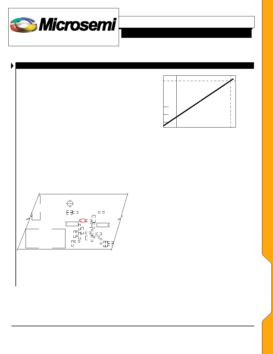
inverter malfunction (see Absolute Maximum Ratings).
-100mV
0V
2.5V
.070
.14
0.7
7
V
BRT_ADJ(V)
I OLAMP
(mA)
Figure 9 – Average Lamp Current vs. V
BRITE Voltage (per Lamp)
CN
2
C30
U9
T1
R5
8
C3
2
C33
R5
9
C3
5
R2
2
R48
R62
R63
R60
R31
R57
R5
5
R5
2
R54
R53
R5
6
R51
Q11
R5
0
C3
9
R4
9 R89
C37
R61
Q10
Backside of Module
U7
Figure 10 – Locating The Resistor on the LXM1621-xx
2.
By making a resistor value change on the module.
Remove R61 for maximum dimming range or increase R61
value to desired minimum dim range setting (see figure 10).
Care should be exercised since at a low enough dim setting the
inverter will be unable to detect that the lamp has started and
will initiate lamp strike (kickoff) voltage. This will result in
lamp flicker. For repeatable low light levels the BRITE input
DC supply must be a very clean stable voltage source, at low
dim inputs.
If you plan to completely remove R61 it is recommended that
you ensure that a minimum voltage above zero remain on the
BRITE input to prevent the above flicker problem.
This
minimum voltage may need to be adjusted for each individual
inverter module. If you are using a pot to control the BRITE
input then a separate trim pot on the low side would accomplish
the same goal.
Both methods discussed will provide a lower duty cycle
operation than is necessary in a 100:1 dimming application.
Careful consideration should be made with regard to display
quality at these dimming levels. At very low brightness levels,
even very small amounts of noise on the VBRITE line can cause
flicker on the display, so special care must be given to
grounding, filtering, and shielding the inverter from the digital
logic and clock signals.
AA
PP
LL
IICC
AA
TT
IIOO
NN
SS
相关PDF资料 |
PDF描述 |
|---|---|
| LZ2111J | SPECIALTY ANALOG CIRCUIT, CDIP20 |
| LZ2112J | SPECIALTY ANALOG CIRCUIT, CDIP20 |
| LZ2121J | SPECIALTY ANALOG CIRCUIT, CDIP20 |
| LZ2122J | SPECIALTY ANALOG CIRCUIT, CDIP20 |
| LZ22251 | SPECIALTY ANALOG CIRCUIT, CDIP22 |
相关代理商/技术参数 |
参数描述 |
|---|---|
| LXM1621-XX | 制造商:MICROSEMI 制造商全称:Microsemi Corporation 功能描述:DIGITAL DIMMING DUAL LAMP CCFL INVERTER MODULE |
| LXM1622-05-01 | 制造商:未知厂家 制造商全称:未知厂家 功能描述:CCFL Inverter Module - Dual Lamp |
| LXM1622-05-02 | 制造商:未知厂家 制造商全称:未知厂家 功能描述:CCFL Inverter Module - Dual Lamp |
| LXM1622-05-03 | 制造商:未知厂家 制造商全称:未知厂家 功能描述:CCFL Inverter Module - Dual Lamp |
| LXM1622-05-XX | 制造商:MICROSEMI 制造商全称:Microsemi Corporation 功能描述:DUAL 5W, DIGITAL DIMMING CCFL INVERTER MODULE |
发布紧急采购,3分钟左右您将得到回复。