- 您现在的位置:买卖IC网 > PDF目录369885 > LXT310JE PCM Transceiver PDF资料下载
参数资料
| 型号: | LXT310JE |
| 英文描述: | PCM Transceiver |
| 中文描述: | 收发器的PCM |
| 文件页数: | 8/26页 |
| 文件大小: | 402K |
| 代理商: | LXT310JE |
LXT310
—
T1 CSU/ISDN PRI Transceiver
8
Datasheet
19
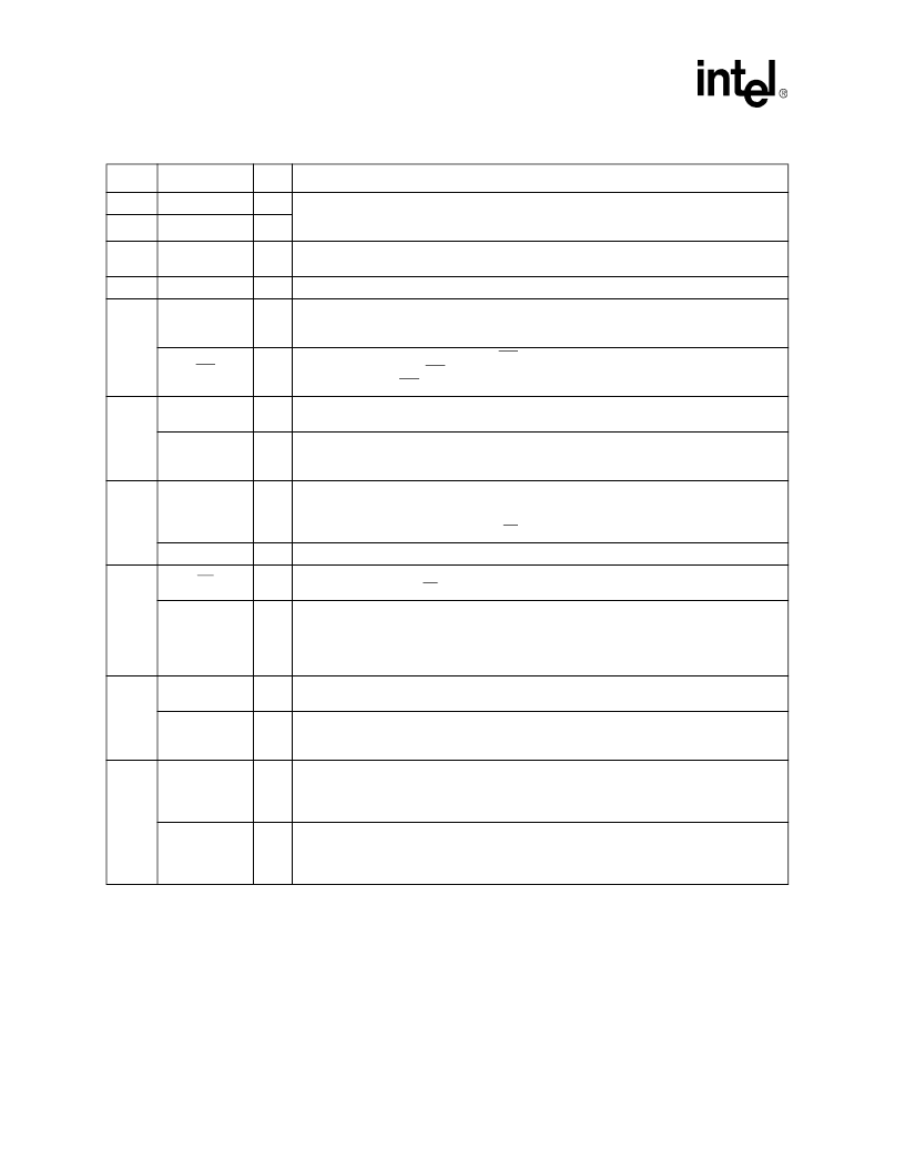
RTIP
I
Receive Tip; Receive Ring.
The AMI signal received from the line is applied at these pins.
A 1:1 transformer is required. Data and clock from the signal applied at these pins are
recovered and output on the RPOS/RNEG and RCLK pins.
20
RRING
I
21
RV+
–
Receive Power Supply.
+5 VDC power supply for all circuits except the transmit drivers.
(Transmit drivers are supplied by TV+.)
22
RGND
–
Receive Ground.
Ground return for power supply RV+.
23
NLOOP
O
Network Loopback
(H/W mode)
.
When High, indicates Inband Network Loopback has been
activated by reception of 00001 pattern for five seconds. NLOOP is reset by reception of 001
for five seconds, or by activation of RLOOP or LLOOP.
INT
O
Interrupt
(Host mode)
.
In Host mode INT goes Low to flag the host processor when LOS or
NLOOP changes state.
INT
is an open-drain output and should be tied to power supply RV+
through a resistor.
INT
is reset by clearing the LOS or NLOOP register bit.
24
SDI
I
Serial Data In
(Host mode)
.
The serial data input stream is applied to this pin when the
LXT310 operates in the Host mode. SDI is sampled on the rising edge of SCLK.
LBO1
I
Line Build-Out Select 1
(H/W mode)
.
In Hardware mode LBO1 works in conjunction with
LBO2 to select the transmit line build-outs: 00 = 0 dB, 01 = 7.5 dB, 10 = 15 dB, and 11 = 22.5
dB.
25
SDO
O
Serial Data Out
(Host mode)
.
The serial data from the LXT310 register is output on this pin
in Host mode. If CLKE is High, SDO is valid on the rising edge of SCLK. If CLKE is Low,
SDO is valid on the falling edge of SCLK. This pin goes to a high-impedance state when the
serial port is being written to and when
CS
is High.
LBO2
I
Line Build-Out Select 2
(H/W mode)
.
Refer to LBO1 signal description.
26
CS
I
Chip Select
(Host mode)
.
This pin selects the serial interface in the Host mode. For each
read or write operation,
CS
must transition from High to Low, and remain Low.
RLOOP
I
Remote Loopback
(H/W mode)
.
This pin controls loopback in the Hardware mode. Setting
RLOOP High enables Remote Loopback. During Remote Loopback, in-line encoders and
decoders are bypassed. Setting both RLOOP and LLOOP High, while holding TAOS Low,
causes a Reset. Setting both RLOOP and LLOOP High, with TAOS High (or tying RCLK to
RLOOP), enables Network Loopback detection.
27
SCLK
I
Serial Clock
(Host mode)
.
This clock is used in the Host mode to write data to or read data
from the serial interface registers.
LLOOP
I
Local Loopback
(H/W mode)
.
This input controls loopback functions in the Hardware mode.
Setting LLOOP High enables the Local Loopback mode. Setting both LLOOP and RLOOP
High, while holding TAOS Low, causes a Reset.
28
CLKE
I
Clock Edge Select
(Host mode)
.
Setting CLKE High causes RPOS and RNEG to be valid
on the falling edge of RCLK, and SDO to be valid on the rising edge of SCLK. When CLKE is
Low, RPOS and RNEG are valid on the rising edge of RCLK, and SDO is valid on the falling
edge of SCLK.
TAOS
I
Transmit All Ones
(H/W mode)
.
When set High in the Hardware mode, TAOS causes the
LXT310 to transmit a stream of marks at the TCLK frequency. Activating TAOS causes
TPOS and TNEG inputs to be ignored. TAOS is inhibited during Remote Loopback. Setting
TAOS, LLOOP and RLOOP High simultaneously enables Network Loopback detection.
Table 1. Pin Descriptions (Continued)
Pin #
Sym
I/O
Description
相关PDF资料 |
PDF描述 |
|---|---|
| LXT310NE | PCM TRANSCEIVER|SINGLE|T-1(DS1)|CMOS|DIP|28PIN|PLASTIC |
| LXT316NE | PCM Repeater |
| LXT316PE | PCM Repeater |
| LXT318NE | PCM TRANSCEIVER|SINGLE|CEPT PCM-30/E-1|CMOS|DIP|28PIN|PLASTIC |
| LXT318PE | PCM TRANSCEIVER|SINGLE|CEPT PCM-30/E-1|CMOS|LDCC|28PIN|PLASTIC |
相关代理商/技术参数 |
参数描述 |
|---|---|
| LXT310NE | 制造商:LEVEL ONE 功能描述: |
| LXT310PE | 制造商:Intel 功能描述: 制造商:LEVEL_ONE 功能描述: 制造商:LEVEL ONE 功能描述:PCM TRANSCEIVER, Single, T-1(DS1), 28 Pin, Plastic, PLCC |
| LXT310PE-IJC8 | 制造商:LEVE ONE 功能描述:310PE-IJC8 |
| LXT310PE-IQC8 | 制造商:LEVEL ONE 功能描述:310PE-IQC8 |
| LXT312 | 制造商:LVL1 制造商全称:LVL1 功能描述:Low Power T1 PCM Repeaters/Transceivers |
发布紧急采购,3分钟左右您将得到回复。