- 您现在的位置:买卖IC网 > PDF目录383294 > M35062-001SP (Mitsubishi Electric Corporation) SCREEN CHARACTER and PATTERN DISPLAY CONTROLLERS PDF资料下载
参数资料
| 型号: | M35062-001SP |
| 厂商: | Mitsubishi Electric Corporation |
| 英文描述: | SCREEN CHARACTER and PATTERN DISPLAY CONTROLLERS |
| 中文描述: | 电影中的角色和模式显示控制器 |
| 文件页数: | 9/44页 |
| 文件大小: | 287K |
| 代理商: | M35062-001SP |
第1页第2页第3页第4页第5页第6页第7页第8页当前第9页第10页第11页第12页第13页第14页第15页第16页第17页第18页第19页第20页第21页第22页第23页第24页第25页第26页第27页第28页第29页第30页第31页第32页第33页第34页第35页第36页第37页第38页第39页第40页第41页第42页第43页第44页
MITSUBISHI MICROCOMPUTERS
M35062-XXXSP
SCREEN CHARACTER and PATTERN DISPLAY CONTROLLERS
9
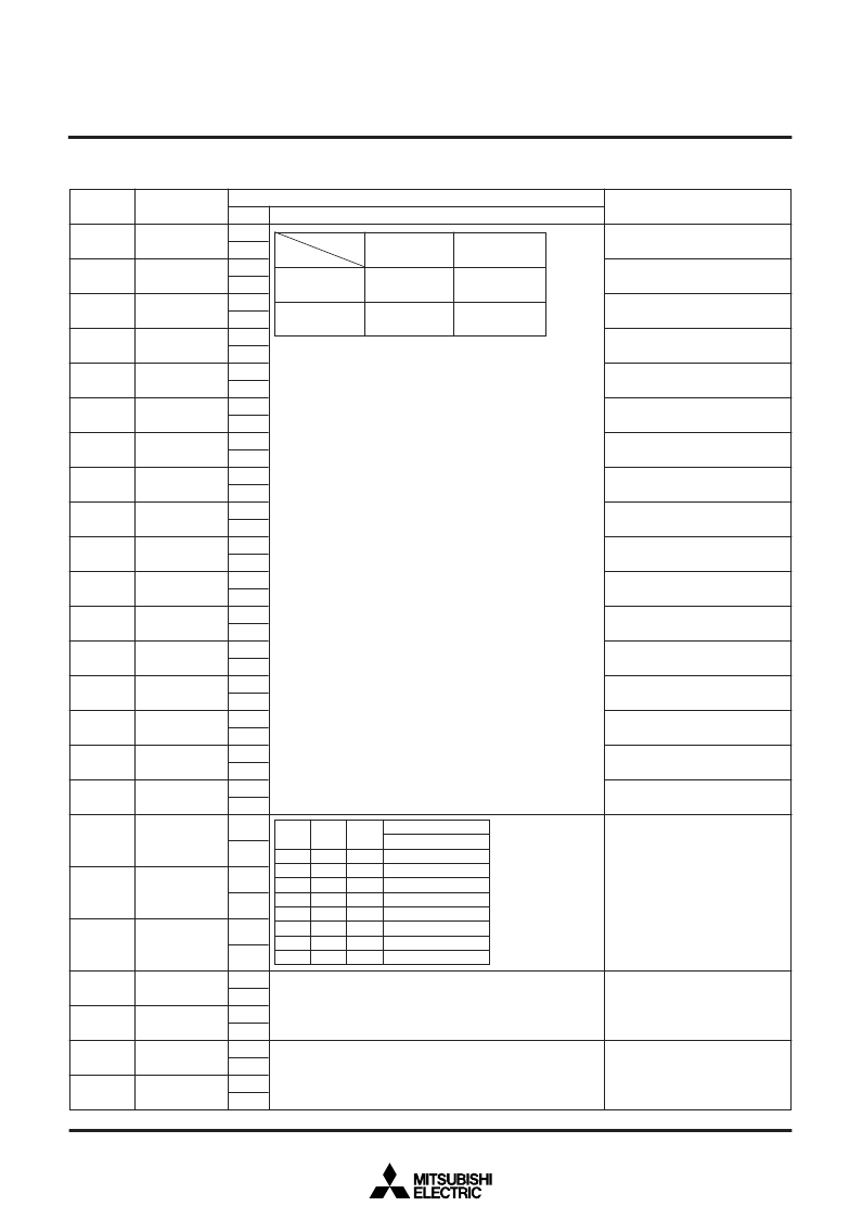
(4) Address 2AB
16
DSP0 00
DSP0 01
DSP0 02
DSP0 03
DSP0 04
DSP0 05
DSP0 06
DSP0 07
DSP0 08
DSP0 09
DSP0 10
DSP0 11
DSP0 12
DSP0 13
DSP0 14
DSP0 15
DSP0 16
PHASE 0
PHASE 1
PHASE 2
TEST25
TEST26
—
—
0
1
2
3
4
5
6
7
8
9
A
B
C
D
E
F
10
11
12
13
14
15
16
17
0
1
0
1
0
1
0
1
0
1
0
1
0
1
0
1
0
1
0
1
0
1
0
1
0
1
0
1
0
1
0
1
0
1
0
1
0
1
0
1
0
1
0
1
0
1
0
1
Status
DA
Register
Contents
Function
Remarks
Set to line 0 of display RAM
Set to line 1 of display RAM
Set to line 2 of display RAM
Set to line 3 of display RAM
Set to line 4 of display RAM
Set to line 5 of display RAM
Set to line 6 of display RAM
Set to line 7 of display RAM
Set to line 8 of display RAM
Set to line 9 of display RAM
Set to line 10 of display RAM
Set to line 11 of display RAM
Set to line 12 of display RAM
Set to line 13 of display RAM
Set to line 14 of display RAM
Set to line 15 of display RAM
Set to line 16 of display RAM
Set by combination of DSP
0XX
(address 2AB
16
) and DSP
1XX
(address 2AC
16
).
At internal synchronous mode (EX = 1), display monitor signal
area is all blanking signal (BLNK output) area.
Note: For half-tone display, it is necessary to input the external
composite video signal to the CVIN pin, and externally
connect a 100 to 200
resistor in series. However, the
half-tone display is possible only with superimposed
displays.
0
Character
Matrix-outline
1
Border
Halftone
(Note)
0
1
DSP0XX
DSP1XX
Raster color setting.
At PHASE 2 through 0 =101,
video signal output is gray, and
RGB output is magenta.
Refer Fig 3 about phase angle.
SELCOR=0
Black
Red
Green
Yellow
Blue
Gray
Cyan
White
Color
0
1
0
1
0
1
0
1
0
0
1
1
0
0
1
1
PHASE
0
PHASE
1
PHASE
2
0
0
0
0
1
1
1
1
Test mode (Must be cleared to 0.)
Must be cleared to 0.
相关PDF资料 |
PDF描述 |
|---|---|
| M35062 | SCREEN CHARACTER and PATTERN DISPLAY CONTROLLERS |
| M35SP-11NK | Thinnest body among the Model series with 35 Diameter |
| M366S1623DT0-C75 | PC133 Unbuffered DIMM |
| M366S1623DT0-C7A | PC133 Unbuffered DIMM |
| M366S1623DT0 | PC100 Unbuffered DIMM |
相关代理商/技术参数 |
参数描述 |
|---|---|
| M35062-XXXSP | 制造商:RENESAS 制造商全称:Renesas Technology Corp 功能描述:SCREEN CHARACTER and PATTERN DISPLAY CONTROLLERS |
| M3506-KIT-380-3 | 制造商:Bonitron 功能描述:REGULATOR FOR VFDS |
| M3506-KIT-380-3-80 | 制造商:Bonitron 功能描述:REGULATOR FOR VFDS |
| M3506-KIT-380-6 | 制造商:Bonitron 功能描述:REGULATOR FOR VFDS |
| M3506-KIT-380-6-80 | 制造商:Bonitron 功能描述:REGULATOR FOR VFDS |
发布紧急采购,3分钟左右您将得到回复。