- 您现在的位置:买卖IC网 > PDF目录98005 > M37224M3-XXXSP 8-BIT, MROM, 8 MHz, MICROCONTROLLER, PDIP42 PDF资料下载
参数资料
| 型号: | M37224M3-XXXSP |
| 元件分类: | 微控制器/微处理器 |
| 英文描述: | 8-BIT, MROM, 8 MHz, MICROCONTROLLER, PDIP42 |
| 封装: | 0.600 INCH, 1.778 MM PITCH, SHRINK, PLASTIC, DIP-42 |
| 文件页数: | 48/83页 |
| 文件大小: | 901K |
| 代理商: | M37224M3-XXXSP |
第1页第2页第3页第4页第5页第6页第7页第8页第9页第10页第11页第12页第13页第14页第15页第16页第17页第18页第19页第20页第21页第22页第23页第24页第25页第26页第27页第28页第29页第30页第31页第32页第33页第34页第35页第36页第37页第38页第39页第40页第41页第42页第43页第44页第45页第46页第47页当前第48页第49页第50页第51页第52页第53页第54页第55页第56页第57页第58页第59页第60页第61页第62页第63页第64页第65页第66页第67页第68页第69页第70页第71页第72页第73页第74页第75页第76页第77页第78页第79页第80页第81页第82页第83页
M37224M3-XXXSP
MITSUBISHI MICROCOMPUTERS
SINGLE-CHIP 8-BIT CMOS MICROCOMPUTER for VOLTAGE SYNTHESIZER
with ON-SCREEN DISPLAY CONTROLLER
52
XIN
XOUT
CIN
M37224M3-XXXSP
COUT
20
19
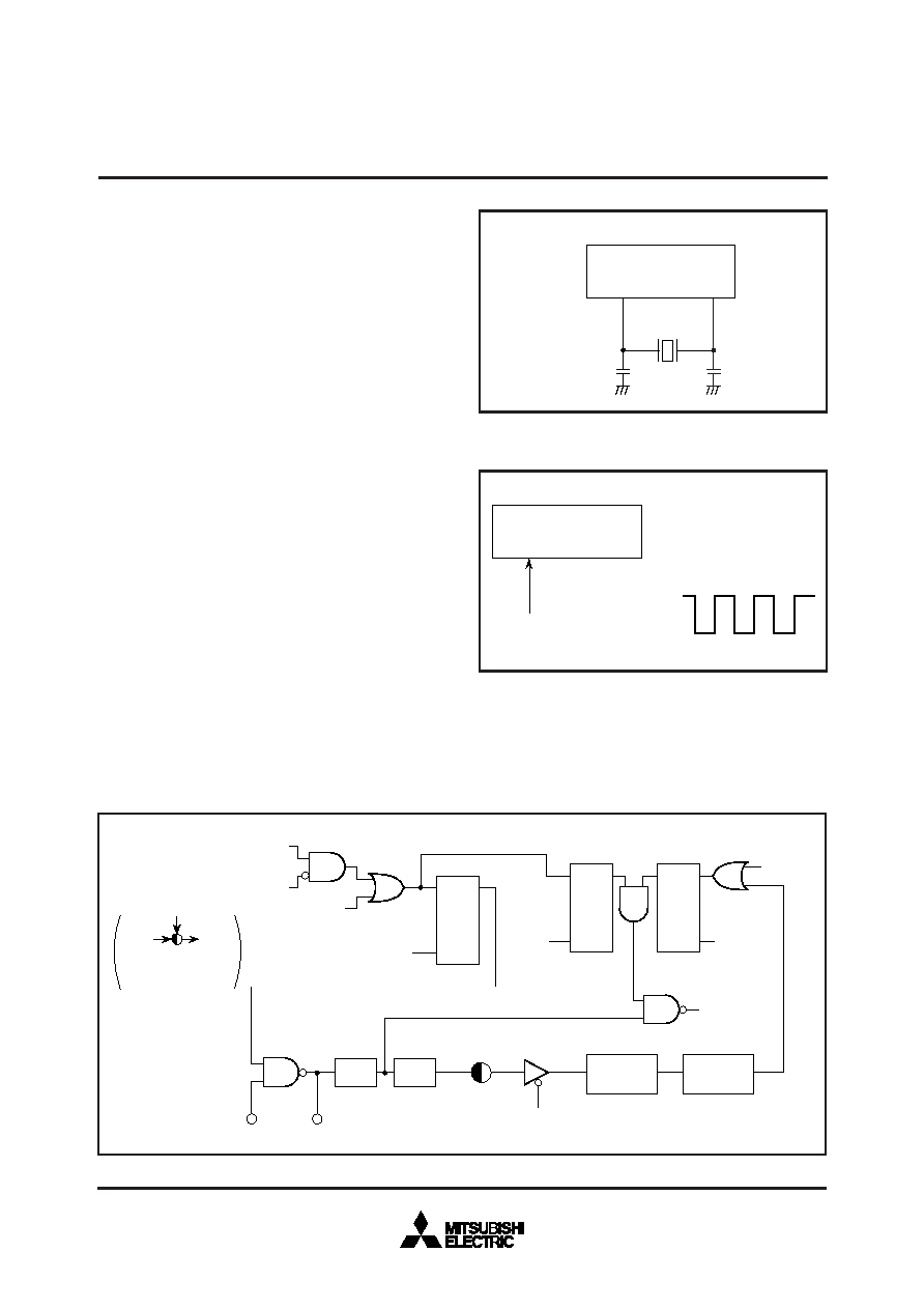
CLOCK GENERATING CIRCUIT
The built-in clock generating circuit is shown in Figure 57. When the
STP instruction is executed, the internal clock
φ stops at HIGH. At
the same time, timers 3 and 4 are connected by hardware and “FF16”
is set in timer 3 and “0716” is set in the timer 4. Select f(XIN)/16 as the
timer 3 count source (set bit 0 of the timer 34 mode register to “0”
before the execution of the STP instruction). Moreover, set the timer
3 and timer 4 interrupt enable bits to disabled (“0”) before execution
of the STP instruction). The oscillator restarts when external inter-
rupt is accepted. However, the internal clock
φ keeps its HIGH until
timer 4 overflows, allowing time for oscillation stabilization when a
ceramic resonator or a quartz-crystal oscillator is used.
When the WIT instruction is executed, the internal clock
φ stops in
the HIGH but the oscillator continues running. This wait state is re-
leased when an interrupt is accepted (Note). Since the oscillator does
not stop, the next instruction can be executed at once.
When returning from the stop or the wait state, to accept an interrupt,
set the corresponding interrupt enable bit to “1” before executing the
STP or the WIT instructions.
Note: In the wait mode, the following interrupts are invalid.
(1) VSYNC interrupt
(2) CRT interrupt
(3) f(XIN)/4096 interrupt
(4) Timer 1 interrupt using f(XIN)/4096 as count source
(5) Timer 2 interrupt using P24/TIM2 pin input as count source
(6) Timer 3 interrupt using P23/TIM3 pin input as count source
(7) Timer 4 interrupt using f(XIN)/2 as count source
(8) Multi-master I2C-BUS interface interrupt
A circuit example using a ceramic resonator (or a quartz-crystal os-
cillator) is shown in Figure 55. Use the circuit constants in accor-
dance with the resonator manufacture’s recommended values. A cir-
cuit example with external clock input is shown in Figure 56. Input
the clock to the XIN pin, and open the XOUT pin.
Fig. 57. Clock Generating Circuit Block Diagram
Fig. 56. External Clock Input Circuit Example
Fig. 55. Ceramic Resonator Circuit Example
XIN
M37224M3-XXXSP
19
Vcc
Vss
External oscillation circuit
Interrupt request
Interrupt disable
flag I
Reset
SQ
R
STP instruction
SQ
R
WIT
instruction
S
Q
R
STP
instruction
Reset
Internal clock
1/2
1/8
Timer 3
Timer 4
XOUT
XIN
T34M0
T34M2
Selection gate :
Connected to black
side at reset.
T34M : Timer 34 mode
register
相关PDF资料 |
PDF描述 |
|---|---|
| M37270MF-XXXSP | 8-BIT, MROM, 8.1 MHz, MICROCONTROLLER, PDIP64 |
| M37273MFH-XXXSP | 8-BIT, MROM, 8.1 MHz, MICROCONTROLLER, PDIP52 |
| M3727GM8-XXXSP | 8-BIT, MROM, 8.1 MHz, MICROCONTROLLER, PDIP42 |
| M37280MFH-XXXSP | 8-BIT, MROM, 8 MHz, MICROCONTROLLER, PDIP64 |
| M37280MKH-XXXSP | 8-BIT, MROM, 8 MHz, MICROCONTROLLER, PDIP64 |
相关代理商/技术参数 |
参数描述 |
|---|---|
| M37225ECSP | 制造商:MITSUBISHI 制造商全称:Mitsubishi Electric Semiconductor 功能描述:SINGLE-CHIP 8-BIT CMOS MICROCOMPUTER for VOLTAGE SYNTHESIZER with ON-SCREEN DISPLAY CONTROLLER |
| M37225M6 | 制造商:RENESAS 制造商全称:Renesas Technology Corp 功能描述:SNGLE-CHIP 8-BIT CMOS MICROCOMPUTER for VOLTAGE SYNTHESIZER with ON-SCREEN DISPLAY CONTROLLER |
| M37225M8 | 制造商:RENESAS 制造商全称:Renesas Technology Corp 功能描述:SNGLE-CHIP 8-BIT CMOS MICROCOMPUTER for VOLTAGE SYNTHESIZER with ON-SCREEN DISPLAY CONTROLLER |
| M37225MA | 制造商:RENESAS 制造商全称:Renesas Technology Corp 功能描述:SNGLE-CHIP 8-BIT CMOS MICROCOMPUTER for VOLTAGE SYNTHESIZER with ON-SCREEN DISPLAY CONTROLLER |
| M372429100 | 制造商:ITW Switches 功能描述:IN-RUSH |
发布紧急采购,3分钟左右您将得到回复。