- 您现在的位置:买卖IC网 > PDF目录80460 > M37544M2-XXXSP 8-BIT, MROM, 8 MHz, MICROCONTROLLER, PDIP32 PDF资料下载
参数资料
| 型号: | M37544M2-XXXSP |
| 元件分类: | 微控制器/微处理器 |
| 英文描述: | 8-BIT, MROM, 8 MHz, MICROCONTROLLER, PDIP32 |
| 封装: | 0.400 INCH, 1.78 MM PITCH, PLASTIC, SDIP-32 |
| 文件页数: | 32/70页 |
| 文件大小: | 645K |
| 代理商: | M37544M2-XXXSP |
第1页第2页第3页第4页第5页第6页第7页第8页第9页第10页第11页第12页第13页第14页第15页第16页第17页第18页第19页第20页第21页第22页第23页第24页第25页第26页第27页第28页第29页第30页第31页当前第32页第33页第34页第35页第36页第37页第38页第39页第40页第41页第42页第43页第44页第45页第46页第47页第48页第49页第50页第51页第52页第53页第54页第55页第56页第57页第58页第59页第60页第61页第62页第63页第64页第65页第66页第67页第68页第69页第70页
7544 Group
Rev.1.04
2004.06.08
page 36 of 66
REJ03B0012-0104Z
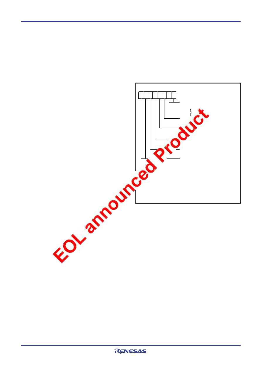
Fig. 44 Structure of CPU mode register
(1) Oscillation control
Stop mode
When the STP instruction is executed, the internal clock
φ stops at
an “H” level and the XIN oscillator stops. At this time, timer 1 is set
to “0116” and prescaler 1 is set to “FF16” when the oscillation sta-
bilization time set bit after release of the STP instruction is “0”. On
the other hand, timer 1 and prescaler 1 are not set when the
above bit is “1”. Accordingly, set the wait time fit for the oscillation
stabilization time of the oscillator to be used. Single selected by
the timer 1 count source selection bit is connected to the input of
prescaler 1. When an external interrupt is accepted, oscillation is
restarted but the internal clock
φ remains at “H” until timer 1
underflows. As soon as timer 1 underflows, the internal clock
φ is
supplied. This is because when a ceramic/quartz-crystal oscillator
is used, some time is required until a start of oscillation. In case
oscillation is restarted by reset, no wait time is generated. So ap-
______
ply an “L” level to the RESET pin while oscillation becomes stable.
Also, the STP instruction cannot be used while CPU is operating
by an on-chip oscillator.
Wait mode
If the WIT instruction is executed, the internal clock
φ stops at an
“H” level, but the oscillator does not stop. The internal clock re-
starts if a reset occurs or when an interrupt is received. Since the
oscillator does not stop, normal operation can be started immedi-
ately after the clock is restarted. To ensure that interrupts will be
received to release the STP or WIT state, interrupt enable bits
must be set to “1” before the STP or WIT instruction is executed.
■ Notes on clock generating circuit
For use with the oscillation stabilization set bit after release of the
STP instruction set to “1”, set values in timer 1 and prescaler 1 af-
ter fully appreciating the oscillation stabilization time of the
oscillator to be used.
Switch of ceramic/quartz-crystal and RC oscillations
After releasing reset the operation starts by starting an on-chip os-
cillator. Then, a ceramic/quartz-crystal oscillation or an RC
oscillation is selected by setting bit 5 of the CPU mode register.
Double-speed mode
When a ceramic/quartz-crystal oscillation is selected, a double-
speed mode can be used. Do not use it when an RC oscillation is
selected.
CPU mode register
Bits 5, 1 and 0 of CPU mode register are used to select oscillation
mode and to control operation modes of the microcomputer. In or-
der to prevent the dead-lock by error-writing (ex. program
run-away), these bits can be rewritten only once after releasing re-
set. After rewriting it is disable to write any data to the bit. (The
emulator MCU “M37544RSS” is excluded.)
Also, when the read-modify-write instructions (SEB, CLB) are ex-
ecuted to bits 2 to 4, 6 and 7, bits 5, 1 and 0 are locked.
Clock division ratio, XIN oscillation control, on-chip oscillator con-
trol
The state transition shown in Fig. 48 can be performed by setting
the clock division ratio selection bits (bits 7 and 6), XIN oscillation
control bit (bit 4), on-chip oscillator oscillation control bit (bit 3) of
CPU mode register. Be careful of notes on use in Fig. 48.
Processor mode bits (Note 1)
b1 b0
0
0 Single-chip mode
0
1
0
1
Not available
b7
b0
2: These bits are used only when a ceramic/quartz-crystal oscillation is selected.
Note 1: The bit can be rewritten only once after releasing reset. After rewriting
it is disable to write any data to the bit. However, by reset the bit is
initialized and can be rewritten, again.
(It is not disable to write any data to the bit for emulator MCU
“M37544RSS”.)
Do not use these when an RC oscillation is selected.
Oscillation mode selection bit (Note 1)
0 : Ceramic/quartz-crystal oscillation
1 : RC oscillation
CPU mode register
(CPUM: address 003B16, initial value: 8016)
Stack page selection bit
0 : 0 page
1 : 1 page
Clock division ratio selection bits
b7 b6
0
0 : f(
φ ) = f(X
IN
)/2 (High-speed mode)
0
1 : f(
φ ) = f(X
IN
)/8 (Middle-speed mode)
1
0 : applied from on-chip oscillator
1
1 : f(
φ ) = f(X
IN
) (Double-speed mode)(Note 2)
On-chip oscillator oscillation control bit
0 : On-chip oscillator oscillation enabled
1 : On-chip oscillator oscillation stop
XIN oscillation control bit
0 : Ceramic/quartz-crystal or RC oscillation enabled
1 : Ceramic/quartz-crystal or RC oscillation stop
相关PDF资料 |
PDF描述 |
|---|---|
| MB90567PMC | 16-BIT, MROM, 16 MHz, MICROCONTROLLER, PQFP64 |
| M37221MAH-XXXSP | 8-BIT, MROM, 8.1 MHz, MICROCONTROLLER, PDIP42 |
| M38037M8-XXXHP | 8-BIT, MROM, 8.4 MHz, MICROCONTROLLER, PQFP64 |
| M38049FFFP | 8-BIT, FLASH, 8.4 MHz, MICROCONTROLLER, PQFP64 |
| M38049FFHSP | 8-BIT, FLASH, 8.4 MHz, MICROCONTROLLER, PDIP64 |
相关代理商/技术参数 |
参数描述 |
|---|---|
| M37544RSS | 制造商:RENESAS 制造商全称:Renesas Technology Corp 功能描述:SINGLE-CHIP 8-BIT CMOS MICROCOMPUTER |
| M37545G1KP | 制造商:RENESAS 制造商全称:Renesas Technology Corp 功能描述:SINGLE-CHIP 8-BIT CMOS MICROCOMPUTER |
| M37545G2KP | 制造商:RENESAS 制造商全称:Renesas Technology Corp 功能描述:SINGLE-CHIP 8-BIT CMOS MICROCOMPUTER |
| M37545G4GP | 制造商:RENESAS 制造商全称:Renesas Technology Corp 功能描述:SINGLE-CHIP 8-BIT CMOS MICROCOMPUTER |
| M37545G4GP#U0 | 功能描述:MCU 2/5V 16K 32-LQFP QZ-ROM RoHS:是 类别:集成电路 (IC) >> 嵌入式 - 微控制器, 系列:740/38000 标准包装:250 系列:80C 核心处理器:8051 芯体尺寸:8-位 速度:16MHz 连通性:EBI/EMI,I²C,UART/USART 外围设备:POR,PWM,WDT 输入/输出数:40 程序存储器容量:- 程序存储器类型:ROMless EEPROM 大小:- RAM 容量:256 x 8 电压 - 电源 (Vcc/Vdd):4.5 V ~ 5.5 V 数据转换器:A/D 8x10b 振荡器型:内部 工作温度:-40°C ~ 85°C 封装/外壳:68-LCC(J 形引线) 包装:带卷 (TR) |
发布紧急采购,3分钟左右您将得到回复。