参数资料
| 型号: | MA160011 |
| 厂商: | Microchip Technology |
| 文件页数: | 4/13页 |
| 文件大小: | 0K |
| 描述: | DAUGHTER BOARD PICDEM LCD 16F91X |
| 标准包装: | 1 |
| 附件类型: | 子板 |
| 适用于相关产品: | DM163030 |
| 产品目录页面: | 659 (CN2011-ZH PDF) |
| 相关产品: | PIC24FJ96GA010T-I/PT-ND - IC PIC MCU FLASH 96KB 100TQFP PIC24FJ96GA008T-I/PT-ND - IC PIC MCU FLASH 96KB 80TQFP PIC24FJ96GA006T-I/PT-ND - IC PIC MCU FLASH 96KB 64TQFP PIC24FJ64GA010T-I/PT-ND - IC PIC MCU FLASH 64KB 100TQFP PIC24FJ64GA008T-I/PT-ND - IC PIC MCU FLASH 64KB 80TQFP PIC24FJ64GA006T-I/PT-ND - IC PIC MCU FLASH 64KB 64TQFP PIC24FJ128GA010T-I/PT-ND - IC PIC MCU FLASH 128K 100TQFP PIC24FJ128GA008T-I/PT-ND - IC PIC MCU FLASH 128K 80TQFP PIC24FJ128GA006T-I/PT-ND - IC PIC MCU FLASH 128K 64TQFP PIC16F946T-I/PT-ND - IC PIC MCU FLASH 8KX14 64TQFP 更多... |
�� �
�
�MICROCHIP� TECHNOLOGY’S� MICROSOLUTIONS� eNEWSLETTER� -� November� 2005�
�High� Resolution� A/D� Conversion� with� PIC� ?� Microcontrollers�
�the� V� DD� /2� reference� voltage,� it� is� possible�
�to� create� this� reference� using� the� PIC�
��Introduction�
�There� are� several� features� on� newer� Flash-based� PIC� ?� microcontrollers� that� make�
�the� creation� of� a� delta-sigma� Analog-to-Digital� Converter� (ADC)� very� simple� to�
�implement.� These� features� are:� (1)� the� Timer1� gate� input� and� (2)� the� internal� comparator�
�synchronized� to� the� Timer1� clock� source.� Before� discussing� how� these� features� make�
�creating� a� delta-sigma� ADC� easy,� let’s� review� how� such� a� converter� works.�
�How� a� Delta-Sigma� ADC� Works�
�Figure� 1� shows� the� circuit� diagram� for� a� typical� comparator� based� delta-sigma� ADC.�
�Two� resistors� are� used� to� create� a� reference� voltage� of� V� DD� /2� at� the� positive� input� of�
�the� comparator.� The� negative� input� of� the� comparator� is� tied� to� the� analog� input� via� a�
�resistor.� Another� resistor� of� the� same� value� connects� the� negative� input� to� the� output�
�of� the� comparator� via� software.� A� capacitor,� C1,� connects� the� negative� input� of� the�
�comparator� to� ground.�
�Figure� 1:� Delta-Sigma� Converter� Using� a� Standard� Microcontroller�
�The� output� of� the� comparator� is� sampled� at� a� constant� frequency.� When� the� comparator�
�output� is� high,� the� pin� driving� the� negative� input� of� the� comparator� (C� IN� -)� is� driven� high�
�in� the� software.� This� causes� the� voltage� at� C� IN� -� to� increase� until� it� is� above� V� DD� /2.� At�
�this� point,� the� comparator� output� becomes� low� and� the� pin� driving� C� IN� -� is� driven� low� in�
�the� software.� Now� the� voltage� at� C� IN� -� will� fall� until� it� is� below� V� DD� /2.� This� cycle� continues�
�to� repeat� itself.� During� this� process,� two� things� are� measured� —� the� total� number� of�
�samples� and� the� number� of� samples� that� the� comparator� output� is� low� by.� The� ratio� of�
�low� samples� to� total� samples� gives� the� ADC� result.� A� very� high� resolution� is� possible�
�because� the� resolution� is� directly� related� to� the� number� of� times� the� output� is� sampled.�
�This� method� requires� software� to� sample� the� comparator� output� and� then� mirror� this�
�output� on� the� pin� driving� C� IN� -.� A� connection� directly� from� the� comparator� output� to�
�C� IN� -� is� not� possible� because� the� pin� can� only� change� when� the� comparator� output�
�is� sampled.� In� addition,� software� is� used� to� count� the� total� number� of� samples� and�
�the� number� of� samples� that� are� low.� Though� a� PIC� microcontroller� is� very� capable� of�
�performing� this� task,� special� care� must� be� taken� when� creating� the� software� to� ensure�
�the� comparator� is� sampled� at� a� set� time� interval.� Furthermore,� the� PIC� microcontroller� is�
�limited� in� which� tasks� it� is� capable� of� performing� while� the� conversion� is� taking� place.�
�How� a� PIC� ?� Microcontroller� Simplifies� the� Conversion�
�Two� features� on� newer� Flash-based� PIC� microcontrollers� allow� this� task� to� be� accomplished� with�
�fewer� processor� resources� and� with� greater� speed.� These� features� are� the� Timer1� gate� input� and�
�the� option� to� synchronize� the� comparator� output� changes� to� the� Timer1� clock� source.�
�The� comparator� can� be� configured� to� change� only� on� the� falling� edge� of� the� clock� source� for�
�Timer1.� This� makes� it� possible� to� tie� the� comparator� output� directly� to� CIN-� via� a� resistor� because�
�the� output� will� only� change� with� the� Timer1� clock� source.� Software� is� no� longer� required� to�
�sample� the� comparator� output� and� mirror� it� on� the� pin� driving� CIN-.�
�Synchronizing� the� comparator� output� with� the� Timer1� clock� source� ensures� the� comparator� is�
�sampled� at� constant� intervals.� The� Timer1� gate� function� can� be� used� to� count� the� number� of�
�times� that� the� comparator� output� is� low.� With� the� Timer1� gate� functionality� enabled,� Timer1� is� only�
�incremented� when� the� gate� is� active.� (Note� the� Timer1� clock� source� continues� to� run� regardless�
�of� the� Timer1� gate� input.)� The� Timer1� gate� can� be� tied� to� either� the� output� of� the� comparator� or�
�an� external� pin.� The� ability� to� gate� Timer1� with� the� comparator� output� simplifies� the� delta-sigma�
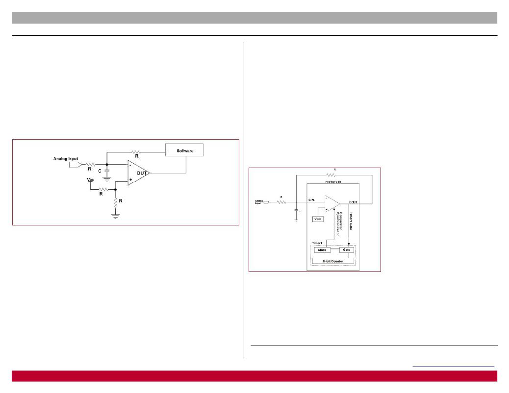
�ADC� conversion.� Figure� 2� shows� the� circuit� with� Timer1� gated� by� the� comparator� output� and� the�
�comparator� synchronized� to� the� Timer1� clock� source.�
�Timer1� is� used� to� count� the� number� of�
�times� the� comparator� output� is� low.� Since�
�Timer0� uses� the� same� clock� source� as�
�Timer1,� the� total� number� of� samples� can�
�be� counted� using� Timer0.� Timer0� is� an�
�8-bit� timer,� whereas� Timer1� is� a� 16-bit�
�timer.� To� complete� a� 16-bit� conversion,�
�the� prescaler� for� Timer0� can� be� set� to�
�1:256� so� that� Timer0� will� interrupt� after�
�65536� (2� 16� )� samples.� Assuming� the�
�microcontroller� is� a� PIC12F683� clocked� by�
�the� internal� 8� MHz� RC� oscillator,� a� 16-bit�
�ADC� conversion� will� take� approximately�
�33� ms.� Note� also� that� instead� of� using� a�
�resistor� divider� circuit� on� C� IN+� to� generate�
�Figure� 2:� Delta-Sigma� Converter� Using� the� PIC12F683�
�Conclusion� microcontroller� ’s� internal� V� REF� circuit.�
�The� Timer1� gate� and� comparator� synchronization� features� are� found� on� many� of� Microchip’s�
�newer� Flash-based� PIC� microcontrollers.� These� features� allow� a� 16-bit� delta-sigma� ADC� to� be�
�implemented� entirely� in� hardware.� Not� only� does� this� allow� for� faster� conversion� times,� but� the�
�PIC� microcontroller� is� free� to� process� other� tasks� while� the� conversion� takes� place.�
�For� more� information� on� delta-sigma� ADC� theory� and� application,� see� Microchip’s� Application�
�Note� AN700� ,� ”Make� a� Delta-Sigma� Converter� Using� a� Microcontroller� ’s� Analog� Comparator�
��Authors:� Reston� A.� Condit,� Senior� Applications� Engineer,� Security,� Microcontroller� &� Technology� Division,�
�Microchip� Technology� Inc� .� Justin� Milks,� Applications� Engineer,� Security,� Microcontroller� &� Technology�
�Division� Microchip� Technology� Inc.�
��Microcontrollers� ?� Digital� Signal� Controllers� ?� Analog� ?� Serial� EEPROMs�
�4�
�相关PDF资料 |
PDF描述 |
|---|---|
| MA180021 | MODULE PLUG-IN 18F87J50 FS USB |
| MA180024 | MODULE PLUG-IN 18F46J50 FS USB |
| MA180028 | MOD PLUG-IN PIC18F87K22 PIM |
| MA2-4-34-625-2-A32-7C | CIRCUIT BREAKER MAG 25A PANEL MT |
| MA240013 | MODULE PLUG-IN PIC24 44-PIN |
相关代理商/技术参数 |
参数描述 |
|---|---|
| MA160012 | 功能描述:子卡和OEM板 PIC16F193x 44P PIM For PIC18 Explorer RoHS:否 制造商:BeagleBoard by CircuitCo 产品:BeagleBone LCD4 Boards 用于:BeagleBone - BB-Bone - Open Source Development Kit |
| MA160012 | 制造商:Microchip Technology Inc 功能描述:PIC16F1937 Plug-in Module for PICDEM PIC |
| MA160014 | 功能描述:子卡和OEM板 PIC18LF45K22 Plug-In Module RoHS:否 制造商:BeagleBoard by CircuitCo 产品:BeagleBone LCD4 Boards 用于:BeagleBone - BB-Bone - Open Source Development Kit |
| MA160015 | 功能描述:子卡和OEM板 PIC16LF1947 PIM RoHS:否 制造商:BeagleBoard by CircuitCo 产品:BeagleBone LCD4 Boards 用于:BeagleBone - BB-Bone - Open Source Development Kit |
| MA160016 | 功能描述:子卡和OEM板 PIC16F1947 PIM RoHS:否 制造商:BeagleBoard by CircuitCo 产品:BeagleBone LCD4 Boards 用于:BeagleBone - BB-Bone - Open Source Development Kit |
发布紧急采购,3分钟左右您将得到回复。