- 您现在的位置:买卖IC网 > PDF目录81613 > MA44631A91 K BAND, SILICON, STEP RECOVERY DIODE PDF资料下载
参数资料
| 型号: | MA44631A91 |
| 元件分类: | 阶跃恢复二极管 |
| 英文描述: | K BAND, SILICON, STEP RECOVERY DIODE |
| 封装: | ROHS COMPLIANT, CERAMIC PACKAGE-2 |
| 文件页数: | 3/5页 |
| 文件大小: | 444K |
| 代理商: | MA44631A91 |
M/A-COM Inc. and its affiliates reserve the right to make changes to the
product(s) or information contained herein without notice. M/A-COM makes
no warranty, representation or guarantee regarding the suitability of its
products for any particular purpose, nor does M/A-COM assume any liability
whatsoever arising out of the use or application of any product(s) or
information.
North America Tel: 800.366.2266 / Fax: 978.366.2266
Europe Tel: 44.1908.574.200 / Fax: 44.1908.574.300
Asia/Pacific Tel: 81.44.844.8296 / Fax: 81.44.844.8298
Visit www.macom.com for additional data sheets and product information.
RoHs Compliant
Silicon Step Recovery Diodes
V4
MA43000, MA44600 Series
3
Electrical Specifications @ TA = +25 °C
Specifications Subject to Change Without Notice.
High Order Step Recovery Diode Varactors for Use in Comb Generation
Part Number
1
Minimum Reverse
Voltage
3
(VR)
Min./Max
Junction
Capacitance
(Cj)
4
Min./Max.
Lifetime
(TL)
Min./Max.
Maximum
Snap Time
(Ts)
5
Maximum
Thermal
Resistance
(
θjc)
Vr=6V
If=10mA/
Ir=6mA
(V)
(pF)
(pS)
(°C/W)
MA43592
25-40
0.20-0.30
9-27
90
70
MA43543
20-50
0.20-0.55
10-25
60
125
Output
Frequency
2
(GHz)
1.00-12.00
2.00-20.00
Maximum
Input
Power
2
(Watts)
1.0
1.5
Case
Style
1
30
93
Notes:
1.
The standard case styles are indicated for eac model number. For other available case styles. consult factory
2.
This is an operable output frequency range and does not imply instantaneous bandwidth.
3.
Reverse voltage (VR) is measured at a reverse bias current of 10A.
4.
Junction capacitance is measured at a reverse voltage of 6V and a frequency of 1MHz.
5.
Transition time is measured between 20% and 80% points on the voltage recovery trace. Test conditions are +10mA and –10 volts.
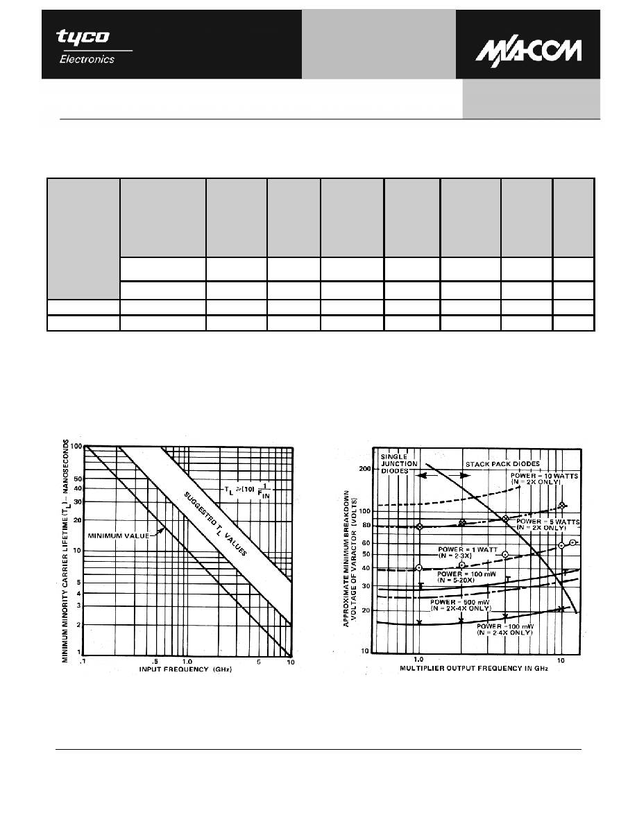
Suggested Design Considerations
Minimum and Suggested Values of Minority
Lifetime (TL) for SRD vs.
Multiplier Input Frequency
Approximate Minimum Breakdown Voltage
Required for SRD at Various Output Power Levels vs.
Output Frequency
相关PDF资料 |
PDF描述 |
|---|---|
| MA44643C30 | K BAND, SILICON, STEP RECOVERY DIODE |
| MA44643C93 | K BAND, SILICON, STEP RECOVERY DIODE |
| MA44641D111 | K BAND, SILICON, STEP RECOVERY DIODE |
| MA48701B30 | mm WAVE BAND, GALLIUM ARSENIDE, STEP RECOVERY DIODE |
| MA48703D32 | mm WAVE BAND, GALLIUM ARSENIDE, STEP RECOVERY DIODE |
相关代理商/技术参数 |
参数描述 |
|---|---|
| MA44631B | 制造商:MA-COM 制造商全称:M/A-COM Technology Solutions, Inc. 功能描述:Step Recovery Diodes |
| MA44631B-91 | 制造商:M/A-COM Technology Solutions 功能描述:VAR CAP SGL 30V - Bulk |
| MA44631C | 制造商:MA-COM 制造商全称:M/A-COM Technology Solutions, Inc. 功能描述:Silicon Step Recovery Diodes |
| MA44641A | 制造商:MA-COM 制造商全称:M/A-COM Technology Solutions, Inc. 功能描述:Silicon Step Recovery Diodes |
| MA44641B | 制造商:MA-COM 制造商全称:M/A-COM Technology Solutions, Inc. 功能描述:Step Recovery Diodes |
发布紧急采购,3分钟左右您将得到回复。