- 您现在的位置:买卖IC网 > PDF目录380325 > MAS3519F (MICRONAS SEMICONDUCTOR HOLDING AG) MAS 35x9F MPEG Layer 2/3, AAC Audio Decoder, G.729 Annex A Codec PDF资料下载
参数资料
| 型号: | MAS3519F |
| 厂商: | MICRONAS SEMICONDUCTOR HOLDING AG |
| 元件分类: | Codec |
| 英文描述: | MAS 35x9F MPEG Layer 2/3, AAC Audio Decoder, G.729 Annex A Codec |
| 中文描述: | 新加坡金融管理局35x9F的MPEG 2 / 3层,AAC音频解码器,G.729的附件A编解码器 |
| 文件页数: | 28/92页 |
| 文件大小: | 1186K |
| 代理商: | MAS3519F |
第1页第2页第3页第4页第5页第6页第7页第8页第9页第10页第11页第12页第13页第14页第15页第16页第17页第18页第19页第20页第21页第22页第23页第24页第25页第26页第27页当前第28页第29页第30页第31页第32页第33页第34页第35页第36页第37页第38页第39页第40页第41页第42页第43页第44页第45页第46页第47页第48页第49页第50页第51页第52页第53页第54页第55页第56页第57页第58页第59页第60页第61页第62页第63页第64页第65页第66页第67页第68页第69页第70页第71页第72页第73页第74页第75页第76页第77页第78页第79页第80页第81页第82页第83页第84页第85页第86页第87页第88页第89页第90页第91页第92页
MAS 35x9F
DATA SHEET
28
June 30, 2004; 6251-505-1DS
Micronas
3.3.2. Data Formats
The internal data word size is 20 bits. All RAM-
addresses can be accessed in a 20-bit mode via I
2
C
bus. Because of the 16-bit width of the I
2
C data regis-
ter the full transfer of all 20 bits requires two 16-bit I
2
C
words. Some commands only access the lower 16 bits
of a cell. For fast access of internal DSP states the
processor core also has an address space of 256 data
registers.
The internal data format is a 20 bit two’s complement
denoted “r”. If in some cases a fixed point notation “v”
is necessary. The conversion between the two forms
of notation is done as follows:
r = v*524288.0+0.5; (
1.0
≤
v < 1.0)
v = r/524288.0; (
524288 < r < 524287)
3.3.2.1. Run and Freeze (Codes 0
hex
to 3
hex
)
The
Run
command causes the start of a program part
at address
a
= (a3,a2,a1,a0). Since nibble a3 is also
the command code (see Table 3–5), it is restricted to
values between 0 and 3. This command is used to
start alternate code or downloaded code from a RAM-
area that has been configured as program RAM.
If the start address is 1000
hex
≤
a
< 3FFF
hex
and the
respective RAM area has been configured as program
RAM (see Table 3–7 on page 31), the MAS 35x9F
continues execution with a custom program already
downloaded to this area.
Example 1: Start program execution at address
345
hex
:
<DW 68 03 45>
Example 2: Start execution of a downloaded code at
address 1000
hex
:
<DW 68 10 00>
Freeze
is a special run command with start address 0.
It suspends all normal program execution. The operat-
ing system will enter an idle loop so that all registers
and memory cells can be watched. This state is useful
for operations like downloading code or contents of
memory cells because the internal program cannot
overwrite these values. This freezing will be required if
alternative software is downloaded into the internal
RAM of the MAS 35x9F.
Freeze has the following I
2
C protocol:
<DW 68 00 00>
The entry point of the default software will be accessed
automatically after a reset, thus issuing a
Run
or
Freeze
command is only necessary for starting down-
loaded software or special program modules which are
not part of the standard set.
3.3.2.2. Read Register (Code A
hex
)
The MAS 35x9F has an address space of 256 DSP-
registers. Some of the registers (
r
= r1,r0 in the figure
above) are direct control inputs for various hardware
blocks, others control the internal program flow. In
Table 3–7, the registers of interest are described in
detail. In contrast to memory cells, registers cannot be
accessed as a block but must always be addressed
individually.
Example:
Read the content of register C8
hex
:
<DW 68 ac 80>
<DW 69 <DR
xx xd dd dd
>
define register
and read
3.3.2.3. Write Register (Code B
hex
)
The controller writes the 20-bit value (
d
= d4,d3,d2,
d1,d0) into the MAS 35x9F register (
r
= r1,r0). A list of
registers needed for control purposes is given in Table
3–7.
Example: Writing the value 81234
hex
into the register
with the number AA
hex
:
<DW 68 ba a8 12 34>
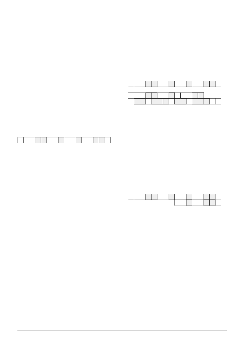
S
DW
data_write
P
a3,a2
a1,a0
W
A
A
A
W
A
1) send command
2) get register value
S
DW
data_write
P
a
,r1
r0,0
S
DW
data_read
N
S
DR
A
P
A
A
d3,d2
W
A
A
A
W
A
W
A
W
A
A
W
W
d1,d0
x,d4
x,x
S
DW
data_write
A
b
,r1
r0,d4
P
d3,d2
d1,d0
W
A
A
W
A
A
W
A
相关PDF资料 |
PDF描述 |
|---|---|
| MAS3529F | MAS 35x9F MPEG Layer 2/3, AAC Audio Decoder, G.729 Annex A Codec |
| MAS3539F | MAS 35x9F MPEG Layer 2/3, AAC Audio Decoder, G.729 Annex A Codec |
| MAS3549F | MAS 35x9F MPEG Layer 2/3, AAC Audio Decoder, G.729 Annex A Codec |
| MAS3587F | MPEG Layer 3 Audio Encoder/Decoder |
| MAS7848L | RDS MODEM / MANCHESTER DECODER |
相关代理商/技术参数 |
参数描述 |
|---|---|
| MAS3529F | 制造商:MICRONAS 制造商全称:MICRONAS 功能描述:MAS 35x9F MPEG Layer 2/3, AAC Audio Decoder, G.729 Annex A Codec |
| MAS3539F | 制造商:MICRONAS 制造商全称:MICRONAS 功能描述:MAS 35x9F MPEG Layer 2/3, AAC Audio Decoder, G.729 Annex A Codec |
| MAS3549F | 制造商:MICRONAS 制造商全称:MICRONAS 功能描述:MAS 35x9F MPEG Layer 2/3, AAC Audio Decoder, G.729 Annex A Codec |
| MAS3559F | 制造商:MICRONAS 制造商全称:MICRONAS 功能描述:MAS 35x9F MPEG Layer 2/3, AAC Audio Decoder, G.729 Annex A Codec |
| MAS3587F | 制造商:未知厂家 制造商全称:未知厂家 功能描述:MPEG Layer 3 Audio Encoder/Decoder |
发布紧急采购,3分钟左右您将得到回复。