参数资料
| 型号: | MAX111BEWE+T |
| 厂商: | Maxim Integrated Products |
| 文件页数: | 10/24页 |
| 文件大小: | 0K |
| 描述: | IC ADC 14BIT 2CH 16-SOIC |
| 产品培训模块: | Lead (SnPb) Finish for COTS Obsolescence Mitigation Program |
| 标准包装: | 1,000 |
| 位数: | 14 |
| 数据接口: | MICROWIRE?,QSPI?,串行,SPI? |
| 转换器数目: | 1 |
| 功率耗散(最大): | 762mW |
| 电压电源: | 单电源 |
| 工作温度: | -40°C ~ 85°C |
| 安装类型: | 表面贴装 |
| 封装/外壳: | 16-SOIC(0.295",7.50mm 宽) |
| 供应商设备封装: | 16-SOIC W |
| 包装: | 带卷 (TR) |
| 输入数目和类型: | 4 个单端,单极;2 个差分,单极 |
MAX110/MAX111
Low-Cost, 2-Channel, ±14-Bit Serial ADCs
18
______________________________________________________________________________________
Selecting the Oversampling
Clock Frequency
Choose the oversampling frequency, fOSC, carefully to
achieve the best relative-accuracy performance from the
MAX110/MAX111 (see
Typical Operating Characteristics).
Clock Divider-Ratio Control Bits
Bits 7 and 8 (DV2 and DV4) program the clock-
frequency divider network. The divider network sets the
frequency ratio between fXCLK (the frequency of the
external TTL/CMOS clock or internal RC oscillator) and
fOSC (the oversampling frequency used by the ADC).
An oversampling clock frequency between 450kHz and
700kHz is optimum for the converter. Best perfor-
mance over the extended temperature range is
obtained by choosing 1MHz or 1.024MHz with the
divide-by-2 option (DV2 = 1) (see the section
Effect
of Dither on INL). To determine the converter’s accura-
cy at other clock frequencies, see the
Typical
Operating Characteristics and Table 5.
Effect of Dither on Relative Accuracy
First-order sigma-delta converters require dither for
randomizing any systematic tone being generated in
the modulator. The frequency of the dither source plays
an important role in linearizing the modulator. The ratio
of the dither generator’s frequency to that of the modu-
lator’s oversampling clock can be changed by setting
the DV2/DV4 bits. The XCLK clock is directly used by
the dither generator while the DV2/DV4 bits reduce the
oversampling clock by a ratio of 2 or 4. Over the com-
mercial temperature range, any ratio (i.e., 1, 2, or 4)
between the dither frequency and the oversampling
clock frequency can be used for best performance.
Over the extended and military temperature ranges, the
ratio of 2 or 4 gives the best performance. See the
Typical Operating Characteristics to observe the effect
of the clock divider on the converter’s linearity.
50Hz/60Hz Line Frequency Rejection
High rejection of 50Hz or 60Hz is obtained by using an
oversampling clock frequency and a clock-cycles/con-
version setting so the conversion time equals an inte-
gral number of line cycles, as in the following equation:
fOSC = fLINE x m / n
where fOSC is the oversampling clock frequency, fLINE
= 50Hz or 60Hz, m is the number of clock cycles per
conversion (see Table 4), and n is the number of line
cycles averaged every conversion.
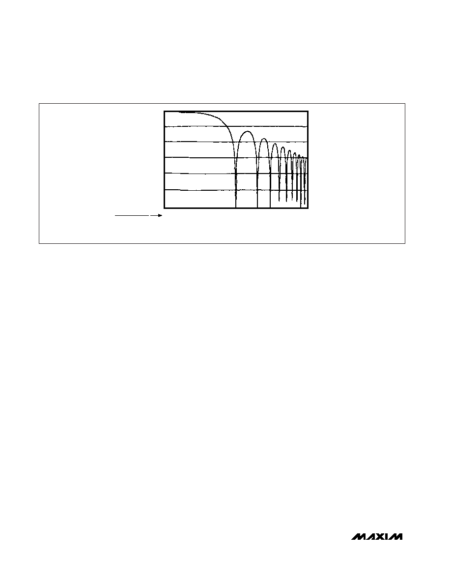
This noise rejection is inherent in integrating and
sigma-delta ADCs, and follows a SIN(X) / X function
(Figure 9). Notches in this function represent extremely
high rejection, and correspond to frequencies with an
integral number of cycles in the MAX110/MAX111’s
selected conversion time.
The shortest conversion time resulting in maximum
simultaneous rejection of both 60Hz and 50Hz line fre-
quencies is 100ms. When using the MAX111, use a
200ms conversion time for maximum 60Hz and 50Hz
rejection and optimum performance. For either device,
select the appropriate oversampling clock frequency
and either an 81,240 or 102,400 clock cycles per con-
version (CCPC) ratio. Table 6 suggests the possible
configurations.
0
-10
-20
-30
-40
-50
-60
0.1
1
CONVERSION TIME
LINE CYCLE PERIOD
SIGNAL FREQUENCY IN Hz
FOR 100ms CONVERSION
TIME (see Table 6)
1
10
20
30
40 50 60 70 80 90100
23
4
5 6 7 8 9 10
GAIN
(dB)
Figure 9. MAX110/MAX111 Noise Rejection Follows SIN(X) / X Function
相关PDF资料 |
PDF描述 |
|---|---|
| MS3100F20-33P | CONN RCPT 11POS WALL MNT W/PINS |
| IDT72285L15PF | IC FIFO 65536X18 LP 15NS 64-TQFP |
| MAX159BEUA+ | IC ADC 10BIT 108KSPS 8-UMAX |
| ISL3176EIUZ-T7A | IC TXRX RS485/422 ESD 10MSOP |
| IDT72V291L20TF | IC FIFO SS 32768X36 20NS 64QFP |
相关代理商/技术参数 |
参数描述 |
|---|---|
| MAX111BMJE | 功能描述:模数转换器 - ADC RoHS:否 制造商:Texas Instruments 通道数量:2 结构:Sigma-Delta 转换速率:125 SPs to 8 KSPs 分辨率:24 bit 输入类型:Differential 信噪比:107 dB 接口类型:SPI 工作电源电压:1.7 V to 3.6 V, 2.7 V to 5.25 V 最大工作温度:+ 85 C 安装风格:SMD/SMT 封装 / 箱体:VQFN-32 |
| MAX111CAP | 制造商:MAXIM 制造商全称:Maxim Integrated Products 功能描述:Analog-to-Digital Converter, 15-Bit |
| MAX111CPE | 制造商:MAXIM 制造商全称:Maxim Integrated Products 功能描述:Analog-to-Digital Converter, 15-Bit |
| MAX111CWE | 制造商:MAXIM 制造商全称:Maxim Integrated Products 功能描述:Analog-to-Digital Converter, 15-Bit |
| MAX111EAP | 制造商:MAXIM 制造商全称:Maxim Integrated Products 功能描述:Analog-to-Digital Converter, 15-Bit |
发布紧急采购,3分钟左右您将得到回复。