参数资料
| 型号: | MAX111BEWE+T |
| 厂商: | Maxim Integrated Products |
| 文件页数: | 11/24页 |
| 文件大小: | 0K |
| 描述: | IC ADC 14BIT 2CH 16-SOIC |
| 产品培训模块: | Lead (SnPb) Finish for COTS Obsolescence Mitigation Program |
| 标准包装: | 1,000 |
| 位数: | 14 |
| 数据接口: | MICROWIRE?,QSPI?,串行,SPI? |
| 转换器数目: | 1 |
| 功率耗散(最大): | 762mW |
| 电压电源: | 单电源 |
| 工作温度: | -40°C ~ 85°C |
| 安装类型: | 表面贴装 |
| 封装/外壳: | 16-SOIC(0.295",7.50mm 宽) |
| 供应商设备封装: | 16-SOIC W |
| 包装: | 带卷 (TR) |
| 输入数目和类型: | 4 个单端,单极;2 个差分,单极 |
MAX110/MAX111
Low-Cost, 2-Channel, ±14-Bit Serial ADCs
______________________________________________________________________________________
19
A 100ms conversion time cannot be achieved with either
10,240 CCPC or 20,480 CCPC modes because fOSC
would be below the minimum 250kHz requirement.
When the gain calibration is performed, the conversion
times change approximately 1% to compensate for the
modulator’s gain error. This slightly degrades the line-
frequency rejection, because the corrected conversion
time is no longer an exact multiple of the line frequency.
Typically, the rejection of 50Hz/60Hz from the converter
is 55dB; i.e., if there is 100mV injection at the reference
or the analog input pin, it will cause an uncertainty of
±0.006%. If the system has large 50Hz/60Hz noise, the
use of internal auto gain calibration is not recommend-
ed. Instead, gain calibration should be done off-chip,
using numerical computation methods.
If you wish to use a configuration other than those sug-
gested in Table 6, you can accomplish similar 50Hz
and 60Hz line-frequency rejection off-chip by averag-
ing several conversions.
__________Applications Information
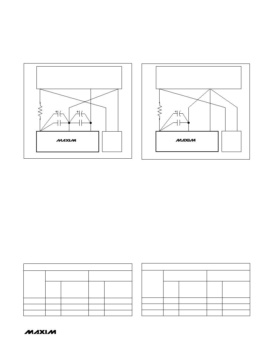
Layout, Grounding, Bypassing
For minimal noise, bypass each supply to GND with a
0.1F capacitor. A ground plane should also be placed
under the analog circuitry. To minimize the coupling
effects of stray capacitance, keep digital lines as far
from analog components and lines as possible. Figure
10 shows the suggested power-supply and ground-
plane connections.
*R = 10
*OPTIONAL
DIGITAL
CIRCUITRY
POWER
SUPPLIES
VDD
VSS
+5V
DGND
+5V
-5V
GND
4.7
F
0.1
F
0.1
F
4.7
F
MAX110
Figure 10a. MAX110 Power-Supply Grounding Connections
*R = 10
*OPTIONAL
DIGITAL
CIRCUITRY
POWER
SUPPLIES
VDD
AGND
+5V
DGND
+5V
GND
4.7
F
0.1
F
MAX111
Figure 10b. MAX111 Power-Supply Grounding Connections
CCPC = Clock Cycles per Conversion
Table 6. Suggested XCLK Frequencies to Achieve Maximum Rejection of Both 50Hz/60Hz Line
Frequencies
MAX111 (tCONVERT = 200ms)
81,240 CCPC
102,400 CCPC
DIVIDER
RATIO
fXCLK
(MHz)
RELATIVE
ACCURACY
(%)
fXCLK
(MHz)
RELATIVE
ACCURACY
(%)
1:1
0.4062
0.030
0.512
0.030
2:1
0.8124
0.025
1.024
0.025
4:1
1.6248
0.022
2.048
0.023
MAX110 (tCONVERT = 100ms)
81,240 CCPC
102,400 CCPC
DIVIDER
RATIO
fXCLK
(MHz)
RELATIVE
ACCURACY
(%)
fXCLK
(MHz)
RELATIVE
ACCURACY
(%)
1:1
0.8124
0.025
1.024
0.065
2:1
1.6248
0.018
2.048
0.045
4:1
3.2496
0.016
4.096
0.030
相关PDF资料 |
PDF描述 |
|---|---|
| MS3100F20-33P | CONN RCPT 11POS WALL MNT W/PINS |
| IDT72285L15PF | IC FIFO 65536X18 LP 15NS 64-TQFP |
| MAX159BEUA+ | IC ADC 10BIT 108KSPS 8-UMAX |
| ISL3176EIUZ-T7A | IC TXRX RS485/422 ESD 10MSOP |
| IDT72V291L20TF | IC FIFO SS 32768X36 20NS 64QFP |
相关代理商/技术参数 |
参数描述 |
|---|---|
| MAX111BMJE | 功能描述:模数转换器 - ADC RoHS:否 制造商:Texas Instruments 通道数量:2 结构:Sigma-Delta 转换速率:125 SPs to 8 KSPs 分辨率:24 bit 输入类型:Differential 信噪比:107 dB 接口类型:SPI 工作电源电压:1.7 V to 3.6 V, 2.7 V to 5.25 V 最大工作温度:+ 85 C 安装风格:SMD/SMT 封装 / 箱体:VQFN-32 |
| MAX111CAP | 制造商:MAXIM 制造商全称:Maxim Integrated Products 功能描述:Analog-to-Digital Converter, 15-Bit |
| MAX111CPE | 制造商:MAXIM 制造商全称:Maxim Integrated Products 功能描述:Analog-to-Digital Converter, 15-Bit |
| MAX111CWE | 制造商:MAXIM 制造商全称:Maxim Integrated Products 功能描述:Analog-to-Digital Converter, 15-Bit |
| MAX111EAP | 制造商:MAXIM 制造商全称:Maxim Integrated Products 功能描述:Analog-to-Digital Converter, 15-Bit |
发布紧急采购,3分钟左右您将得到回复。