- 您现在的位置:买卖IC网 > PDF目录10492 > MAX1181ECM+D (Maxim Integrated Products)IC ADC 10BIT 80MSPS DUAL 48-TQFP PDF资料下载
参数资料
| 型号: | MAX1181ECM+D |
| 厂商: | Maxim Integrated Products |
| 文件页数: | 6/20页 |
| 文件大小: | 0K |
| 描述: | IC ADC 10BIT 80MSPS DUAL 48-TQFP |
| 产品培训模块: | Lead (SnPb) Finish for COTS Obsolescence Mitigation Program |
| 标准包装: | 250 |
| 位数: | 10 |
| 采样率(每秒): | 80M |
| 数据接口: | 并联 |
| 转换器数目: | 2 |
| 功率耗散(最大): | 291mW |
| 电压电源: | 单电源 |
| 工作温度: | -40°C ~ 85°C |
| 安装类型: | 表面贴装 |
| 封装/外壳: | 48-TQFP 裸露焊盘 |
| 供应商设备封装: | 48-TQFP 裸露焊盘(7x7) |
| 包装: | 托盘 |
| 输入数目和类型: | 4 个单端,双极;2 个差分,双极 |
| 产品目录页面: | 1396 (CN2011-ZH PDF) |
MAX1181
Dual 10-Bit, 80Msps, 3V, Low-Power ADC
with Internal Reference and Parallel Outputs
14
______________________________________________________________________________________
The 22pF CIN capacitor acts as a small bypassing
capacitor.
Using Transformer Coupling
An RF transformer (Figure 6) provides an excellent
solution to convert a single-ended source signal to a
fully-differential signal, required by the MAX1181 for
optimum performance. Connecting the center tap of the
transformer to COM provides a VDD / 2 DC level shift to
the input. Although a 1:1 transformer is shown, a step-
up transformer may be selected to reduce the drive
requirements. A reduced signal swing from the input
driver, such as an op amp, may also improve the over-
all distortion.
In general, the MAX1181 provides better SFDR and
THD with fully-differential input signals, than a single-
ended drive, especially for high input frequencies. In
differential input mode, even-order harmonics are lower
as both inputs (INA+, INA- and/or INB+, INB-) are bal-
anced, and each of the ADC inputs only require half the
signal swing compared to single-ended mode.
Single-Ended AC-Coupled Input Signal
Figure 7 shows an AC-coupled, single-ended applica-
tion. Amplifiers, like the MAX4108, provide high-speed,
high bandwidth, low-noise, and low distortion to main-
tain the integrity of the input signal.
Typical QAM Demodulation Application
The most frequently used modulation technique for digi-
tal communications application is the Quadrature
Amplitude Modulation (QAM). QAMs are typically found
in spread-spectrum based systems. A QAM signal rep-
resents a carrier frequency modulated in both amplitude
and phase. At the transmitter, modulating the baseband
signal with quadrature outputs, a local oscillator fol-
lowed by subsequent up-conversion can generate the
QAM signal. The result is an in-phase (I) and a quadra-
ture (Q) carrier component, where the Q component is
90 degrees phase-shifted with respect to the in-phase
component. At the receiver, the QAM signal is divided
down into its I and Q components, essentially represent-
ing the modulation process reversed. Figure 8 displays
the demodulation process performed in the analog
domain, using the dual-matched, 3V, 10-bit ADCs,
MAX1181 and the MAX2451 quadrature demodulators,
to recover and digitize the I and Q baseband signals.
Before being digitized by the MAX1181, the mixed-down
signal components may be filtered by matched analog
filters, such as Nyquist or pulse-shaping filters which
remove any unwanted images from the mixing process,
enhances the overall signal-to-noise (SNR) perfor-
mance, and minimizes intersymbol interference.
Grounding, Bypassing,
and Board Layout
The MAX1181 requires high-speed board layout design
techniques. Locate all bypass capacitors as close to
the device as possible, preferably on the same side as
the ADC, using surface-mount devices for minimum
inductance. Bypass VDD, REFP, REFN, and COM with
two parallel 0.1F ceramic capacitors and a 2.2F
bipolar capacitor to GND. Follow the same rules to
bypass the digital supply (OVDD) to OGND. Multilayer
boards with separate ground and power planes, pro-
duce the highest level of signal integrity. Consider the
use of a split ground plane arranged to match the phys-
ical location of the analog ground (GND) and the digital
output driver ground (OGND) on the ADCs package.
The two ground planes should be joined at a single
point, such that the noisy digital ground currents do not
interfere with the analog ground plane. The ideal loca-
tion of this connection can be determined experimental-
ly at a point along the gap between the two ground
planes, which produces optimum results. Make this
connection with a low-value, surface-mount resistor (1
Ω
to 5
Ω), a ferrite bead, or a direct short. Alternatively, all
ground pins could share the same ground plane, if the
ground plane is sufficiently isolated from any noisy, dig-
ital systems ground plane (e.g., downstream output
buffer or DSP ground plane). Route high-speed digital
signal traces away from the sensitive analog traces of
either channel. Make sure to isolate the analog input
lines to each respective converter to minimize channel-
to-channel crosstalk. Keep all signal lines short and
free of 90 degree turns.
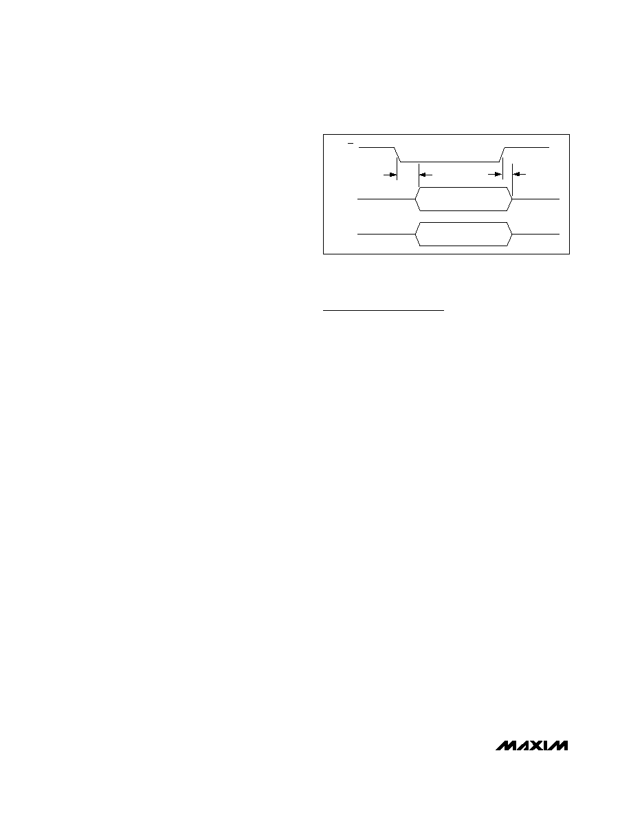
OUTPUT
D9A–D0A
OE
tDISABLE
tENABLE
HIGH IMPEDANCE
VALID DATA
OUTPUT
D9B–D0B
HIGH IMPEDANCE
VALID DATA
Figure 4. Output Timing Diagram
相关PDF资料 |
PDF描述 |
|---|---|
| MAX11040KGUU+ | IC ADC 24BIT 4CH 38-TSSOP |
| UP050SL100J-A-B | CAP CER 10PF 50V 5% AXIAL |
| ICL7109CMH+D | IC ADC 12BIT 3-ST 44-MQFP |
| DS26303LN-120+ | IC LIU E1/T1/J1 3.3V 144-ELQFP |
| MS3116P10-98S | CONN PLUG 6POS STRAIGHT W/SCKT |
相关代理商/技术参数 |
参数描述 |
|---|---|
| MAX1181ECM-TD | 功能描述:模数转换器 - ADC RoHS:否 制造商:Texas Instruments 通道数量:2 结构:Sigma-Delta 转换速率:125 SPs to 8 KSPs 分辨率:24 bit 输入类型:Differential 信噪比:107 dB 接口类型:SPI 工作电源电压:1.7 V to 3.6 V, 2.7 V to 5.25 V 最大工作温度:+ 85 C 安装风格:SMD/SMT 封装 / 箱体:VQFN-32 |
| MAX1181EVKIT | 功能描述:电源管理IC开发工具 RoHS:否 制造商:Maxim Integrated 产品:Evaluation Kits 类型:Battery Management 工具用于评估:MAX17710GB 输入电压: 输出电压:1.8 V |
| MAX1182ECM | 制造商:Rochester Electronics LLC 功能描述: 制造商:Maxim Integrated Products 功能描述: |
| MAX1182ECM+D | 功能描述:模数转换器 - ADC 10-Bit 2Ch 65Msps High Speed ADC RoHS:否 制造商:Texas Instruments 通道数量:2 结构:Sigma-Delta 转换速率:125 SPs to 8 KSPs 分辨率:24 bit 输入类型:Differential 信噪比:107 dB 接口类型:SPI 工作电源电压:1.7 V to 3.6 V, 2.7 V to 5.25 V 最大工作温度:+ 85 C 安装风格:SMD/SMT 封装 / 箱体:VQFN-32 |
| MAX1182ECM+TD | 功能描述:模数转换器 - ADC 10-Bit 2Ch 65Msps High Speed ADC RoHS:否 制造商:Texas Instruments 通道数量:2 结构:Sigma-Delta 转换速率:125 SPs to 8 KSPs 分辨率:24 bit 输入类型:Differential 信噪比:107 dB 接口类型:SPI 工作电源电压:1.7 V to 3.6 V, 2.7 V to 5.25 V 最大工作温度:+ 85 C 安装风格:SMD/SMT 封装 / 箱体:VQFN-32 |
发布紧急采购,3分钟左右您将得到回复。