- 您现在的位置:买卖IC网 > PDF目录10563 > MAX1254BEUE+ (Maxim Integrated Products)IC ADC 12BIT W/REF 16-TSSOP PDF资料下载
参数资料
| 型号: | MAX1254BEUE+ |
| 厂商: | Maxim Integrated Products |
| 文件页数: | 13/29页 |
| 文件大小: | 0K |
| 描述: | IC ADC 12BIT W/REF 16-TSSOP |
| 产品培训模块: | Lead (SnPb) Finish for COTS Obsolescence Mitigation Program |
| 标准包装: | 96 |
| 位数: | 12 |
| 采样率(每秒): | 94k |
| 数据接口: | MICROWIRE?,QSPI?,串行,SPI? |
| 转换器数目: | 1 |
| 功率耗散(最大): | 15mW |
| 电压电源: | 模拟和数字,双 ± |
| 工作温度: | -40°C ~ 85°C |
| 安装类型: | 表面贴装 |
| 封装/外壳: | 16-TSSOP(0.173",4.40mm 宽) |
| 供应商设备封装: | 16-TSSOP |
| 包装: | 管件 |
| 输入数目和类型: | 8 个单端,单极;8 个单端,双极;4 个差分,单极;4 个差分,双极 |
| 产品目录页面: | 1396 (CN2011-ZH PDF) |
第1页第2页第3页第4页第5页第6页第7页第8页第9页第10页第11页第12页当前第13页第14页第15页第16页第17页第18页第19页第20页第21页第22页第23页第24页第25页第26页第27页第28页第29页
MAX1253/MAX1254
Stand-Alone, 10-Channel, 12-Bit System Monitors
with Internal Temperature Sensor and VDD Monitor
20
______________________________________________________________________________________
Setup Register: Scan Mode Bit (B2)
The scan mode bit selects between automatic scan-
ning and manual conversion mode.
When set (B2 = 1), the MAX1253/MAX1254 enter auto-
matic scanning mode and convert every enabled chan-
nel starting with the internal temperature sensor,
followed by the VDD monitor, then sequencing through
AIN0 to AIN7.
After converting all the enabled channels, the
MAX1253/MAX1254 enter a wait state set by the sam-
ple wait bits in the setup register. After completing the
sample wait time, the scan cycle repeats.
When B2 = 0, the MAX1253/MAX1254 are in manual
mode and convert only the selected channel after
receiving a Manually Triggered Conversion command
(see the Manually Triggered Conversion (Command
Code 0000) section). Whether in automatic scanning
mode or manual mode, a Read Current Data Register
for Selected Channel command outputs the last-com-
pleted conversion result for the addressed channel at
DOUT.
Setup Register: Reference Selection Bits (B1, B0)
The MAX1253/MAX1254 can be used with an internal
or external reference. Select between internal and
external reference modes through bits B1 and B0 of the
setup register (see Table 10).
Alarm Register
The alarm register (Table 11) holds the current alarm sta-
tus for all of the monitored signals. This 24-bit register
can only be read and cleared. The alarm register has 2
bits for each external input channel, 2 for the onboard
temperature sensor, and 2 for the VDD monitor (see
Table 12). At power-up, these bits are logic low, indicat-
ing no alarms at any input. When any bit in the alarm reg-
ister is set, INT becomes active and remains active until
all alarm bits are cleared. After a fault counter exceeds
the set threshold, the alarm register bits for that particular
channel are updated to indicate an alarm.
To clear the interrupt, reset the active alarm bit with the
Clear Alarm Register command, Clear Channel Alarm
command, a RESET command, or by writing a new
configuration to the faulting channel. The alarm register
defaults to 000000 hex.
Table 11 illustrates how the alarm register stores the
information on which channel a fault has occurred. The
alarm code for each bit pair is shown in Table 12.
Channel Registers
Each channel (internal temperature sensor, VDD moni-
tor, and AIN0 to AIN7) has registers to hold the conver-
sion result (current data register) and channel-specific
configuration data. The channel-specific configuration
registers include: the upper threshold register, the
lower threshold register, and the channel configuration
register. In differential mode, only the registers for the
even channel of the differential input pair are used. The
channel-specific configuration registers for the odd
channel of a differential channel pair are ignored.
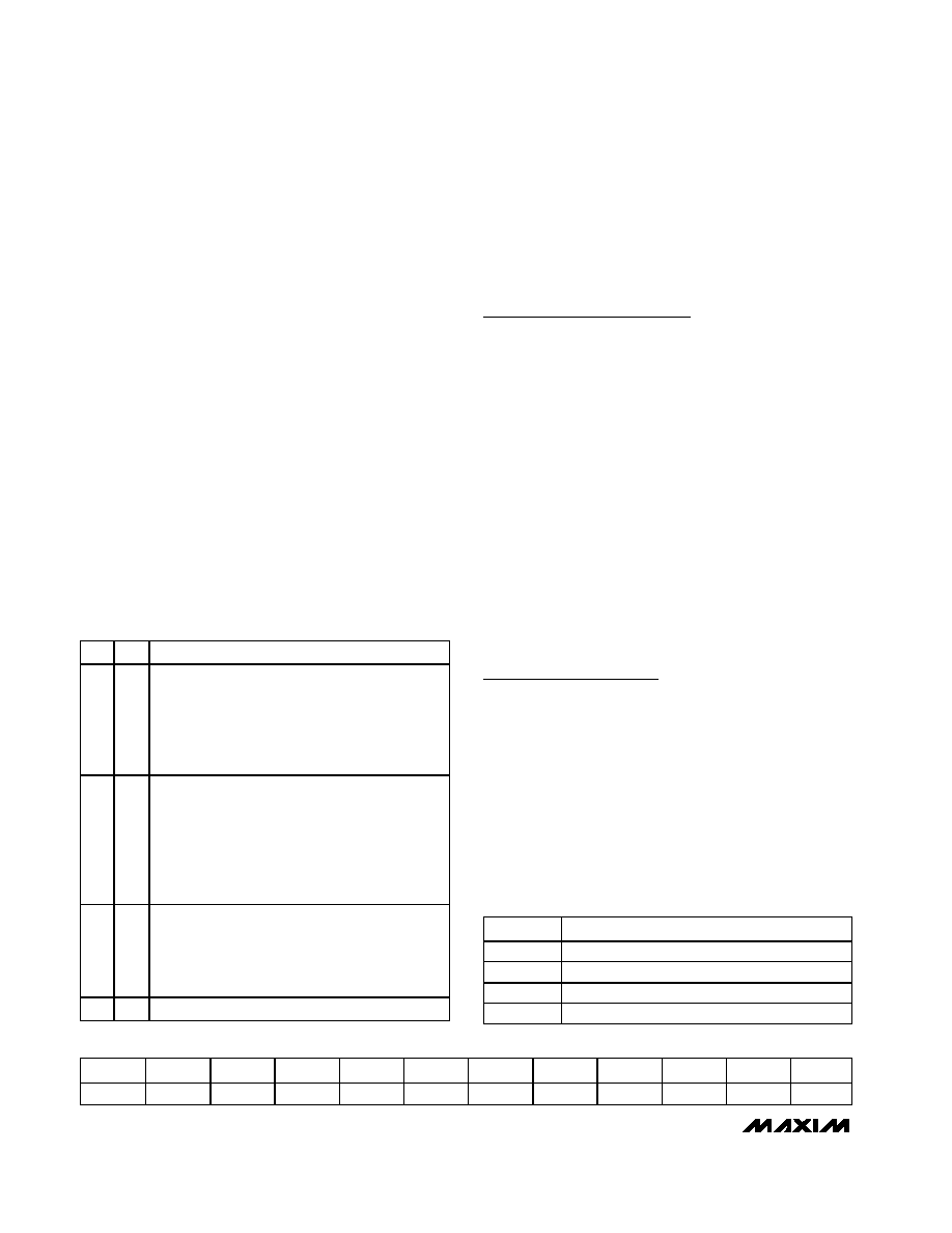
Table 10. Reference Selection
B1
B0
REFERENCE MODE
00
Voltage measurements use external reference,
while temperature measurements use the internal
reference. A 20s reference startup delay is
added prior to each temperature measurement
in this mode. This is the default mode after
power-up and after a software RESET.
01
All measurements use the internal reference. A
40s reference startup delay is added prior to
starting the scanning of enabled channels,
allowing the internal reference to stabilize.
Note: For sample wait times less than 80s, the
reference is continuously powered when in
automatic scan mode.
10
All measurements use the internal reference. By
selecting this mode, the reference is powered up
immediately when CS goes high after writing this
configuration. Once the reference system is
powered up, no further delay is added.
1
Reserved.
Table 11. Alarm Register Format
B23/B22
B21/B20
B19/B18
B17/B16
B15/B14
B13/B12
B11/B10
B9/B8
B7/B6
B5/B4
B3/B2
B1/B0
TEMP
VDD
AIN0
AIN1
AIN2
AIN3
AIN4
AIN5
AIN6
AIN7
Res
Table 12. Alarm Register Coding
(2 Bits/Channel)
CODE
DESCRIPTION
00
No alarm (power-up state)
01
Input is below lower threshold
10
Input is above upper threshold
00
Reserved
相关PDF资料 |
PDF描述 |
|---|---|
| VE-2TF-IW-F4 | CONVERTER MOD DC/DC 72V 100W |
| XRT83D10IW-F | IC LIU T1/E1 SGL 28SOJ |
| VI-J1Z-MW-F1 | CONVERTER MOD DC/DC 2V 40W |
| 206039-1 | CONN PLUG CPC 28POS REV SER 2 |
| 211769-3 | CONN RCPT CPC 9POS REV FREE HANG |
相关代理商/技术参数 |
参数描述 |
|---|---|
| MAX1254BEUE+ | 功能描述:模数转换器 - ADC 12-Bit 10Ch 94ksps 5V Precision ADC RoHS:否 制造商:Texas Instruments 通道数量:2 结构:Sigma-Delta 转换速率:125 SPs to 8 KSPs 分辨率:24 bit 输入类型:Differential 信噪比:107 dB 接口类型:SPI 工作电源电压:1.7 V to 3.6 V, 2.7 V to 5.25 V 最大工作温度:+ 85 C 安装风格:SMD/SMT 封装 / 箱体:VQFN-32 |
| MAX1254BEUE+T | 功能描述:模数转换器 - ADC 12-Bit 10Ch 94ksps 5V Precision ADC RoHS:否 制造商:Texas Instruments 通道数量:2 结构:Sigma-Delta 转换速率:125 SPs to 8 KSPs 分辨率:24 bit 输入类型:Differential 信噪比:107 dB 接口类型:SPI 工作电源电压:1.7 V to 3.6 V, 2.7 V to 5.25 V 最大工作温度:+ 85 C 安装风格:SMD/SMT 封装 / 箱体:VQFN-32 |
| MAX1254BEUE-T | 功能描述:模数转换器 - ADC RoHS:否 制造商:Texas Instruments 通道数量:2 结构:Sigma-Delta 转换速率:125 SPs to 8 KSPs 分辨率:24 bit 输入类型:Differential 信噪比:107 dB 接口类型:SPI 工作电源电压:1.7 V to 3.6 V, 2.7 V to 5.25 V 最大工作温度:+ 85 C 安装风格:SMD/SMT 封装 / 箱体:VQFN-32 |
| MAX1254EVC16 | 功能描述:模数转换器 - ADC Stand-Alone 10-Channel 12-Bit System Monitors with Internal Temperature Sensor and VDD Monitor RoHS:否 制造商:Texas Instruments 通道数量:2 结构:Sigma-Delta 转换速率:125 SPs to 8 KSPs 分辨率:24 bit 输入类型:Differential 信噪比:107 dB 接口类型:SPI 工作电源电压:1.7 V to 3.6 V, 2.7 V to 5.25 V 最大工作温度:+ 85 C 安装风格:SMD/SMT 封装 / 箱体:VQFN-32 |
| MAX1254EVKIT | 功能描述:数据转换 IC 开发工具 Evaluation Kit/Evaluation System for the MAX1254 MAX1253 RoHS:否 制造商:Texas Instruments 产品:Demonstration Kits 类型:ADC 工具用于评估:ADS130E08 接口类型:SPI 工作电源电压:- 6 V to + 6 V |
发布紧急采购,3分钟左右您将得到回复。