- 您现在的位置:买卖IC网 > PDF目录10563 > MAX1254BEUE+ (Maxim Integrated Products)IC ADC 12BIT W/REF 16-TSSOP PDF资料下载
参数资料
| 型号: | MAX1254BEUE+ |
| 厂商: | Maxim Integrated Products |
| 文件页数: | 14/29页 |
| 文件大小: | 0K |
| 描述: | IC ADC 12BIT W/REF 16-TSSOP |
| 产品培训模块: | Lead (SnPb) Finish for COTS Obsolescence Mitigation Program |
| 标准包装: | 96 |
| 位数: | 12 |
| 采样率(每秒): | 94k |
| 数据接口: | MICROWIRE?,QSPI?,串行,SPI? |
| 转换器数目: | 1 |
| 功率耗散(最大): | 15mW |
| 电压电源: | 模拟和数字,双 ± |
| 工作温度: | -40°C ~ 85°C |
| 安装类型: | 表面贴装 |
| 封装/外壳: | 16-TSSOP(0.173",4.40mm 宽) |
| 供应商设备封装: | 16-TSSOP |
| 包装: | 管件 |
| 输入数目和类型: | 8 个单端,单极;8 个单端,双极;4 个差分,单极;4 个差分,双极 |
| 产品目录页面: | 1396 (CN2011-ZH PDF) |
第1页第2页第3页第4页第5页第6页第7页第8页第9页第10页第11页第12页第13页当前第14页第15页第16页第17页第18页第19页第20页第21页第22页第23页第24页第25页第26页第27页第28页第29页
MAX1253/MAX1254
Stand-Alone, 10-Channel, 12-Bit System Monitors
with Internal Temperature Sensor and VDD Monitor
______________________________________________________________________________________
21
Channel Configuration Register
Each channel has a channel configuration register
(Table 13) defining the number of consecutive faults to
be detected before setting the alarm bits and generat-
ing an interrupt, as well as controlling the digital averag-
ing. At power-up and after a RESET command, the
register defaults to 00 hex (no averaging, alarm on first
fault).
Fault Bits
The value stored in the fault bits (B7–B4) in the channel
configuration register sets the number of faults that
must occur for that channel before generating an inter-
rupt. Encoding of the fault bits is straight binary with
valves 0 to 15. A fault occurs in a channel when the
value in its current data register is outside the range
defined by the channel’s upper and lower threshold
registers. For example, if the number of faults set by the
fault bits is N, an interrupt is generated when the num-
ber of consecutive faults (see note below) reach (N +
1). The fault bits default to 0 hex at power-up.
Note: Consecutive faults are those happening in con-
secutive conversion scans for the same channel. If a
fault occurs and the next scan finds the input within the
normal range defined by the thresholds, the fault
counter resets. If the next counter finds the input signal
outside the opposite threshold, rather than the previous
one, the fault counter also resets. The fault counter
increments only when counting consecutive faults
exceeding the same threshold (Figure 4).
Averaging
The averaging calculated by the data-acquisition algo-
rithm of the MAX1253/MAX1254 improves the input sig-
nal-to-noise ratio (SNR) by reducing the signal
bandwidth digitally. The formula below describes the
filter implemented in the MAX1253/MAX1254:
current value = [(N - 1) / N] x past value +
[(present value) / N]
where N = number of samples indicated in Table 14.
The averaging bits (B3–B0) in the channel configuration
register can set the N factor to any value in Table 14.
The output of the filter-running algorithm is continuously
available in the current data register. The starting value
used by the algorithm is the initial state of the current
data register. The current data register is reset to mid-
scale (800 hex) at power-up or after a RESET com-
mand, but it can be loaded with a more appropriate
initial value to improve the filter settling time.
At power-up or after a RESET command, the B3–B0
bits of the channel configuration register are set to 0
hex, corresponding to a number of averaged N = 1, no
averaging. See Table 13 and the Write-Selected
Channel Configuration Registers section for program-
ming details. See Table 14 for N encoding.
As in all digital filters, truncation can be a cause of sig-
nificant errors. In the MAX1253/MAX1254, 24 bits of
precision are maintained in the digital averaging func-
tion, maintaining a worst-case truncation error of well
below an LSB. The worst-case truncation error in the
MAX1253/MAX1254 is given by the following:
where N = number of conversions averaged.
Therefore, the worst truncation error when averaging
256 samples is 0.0623 LSBs.
worst case truncation error
N
LSBs
-
=
1
4096
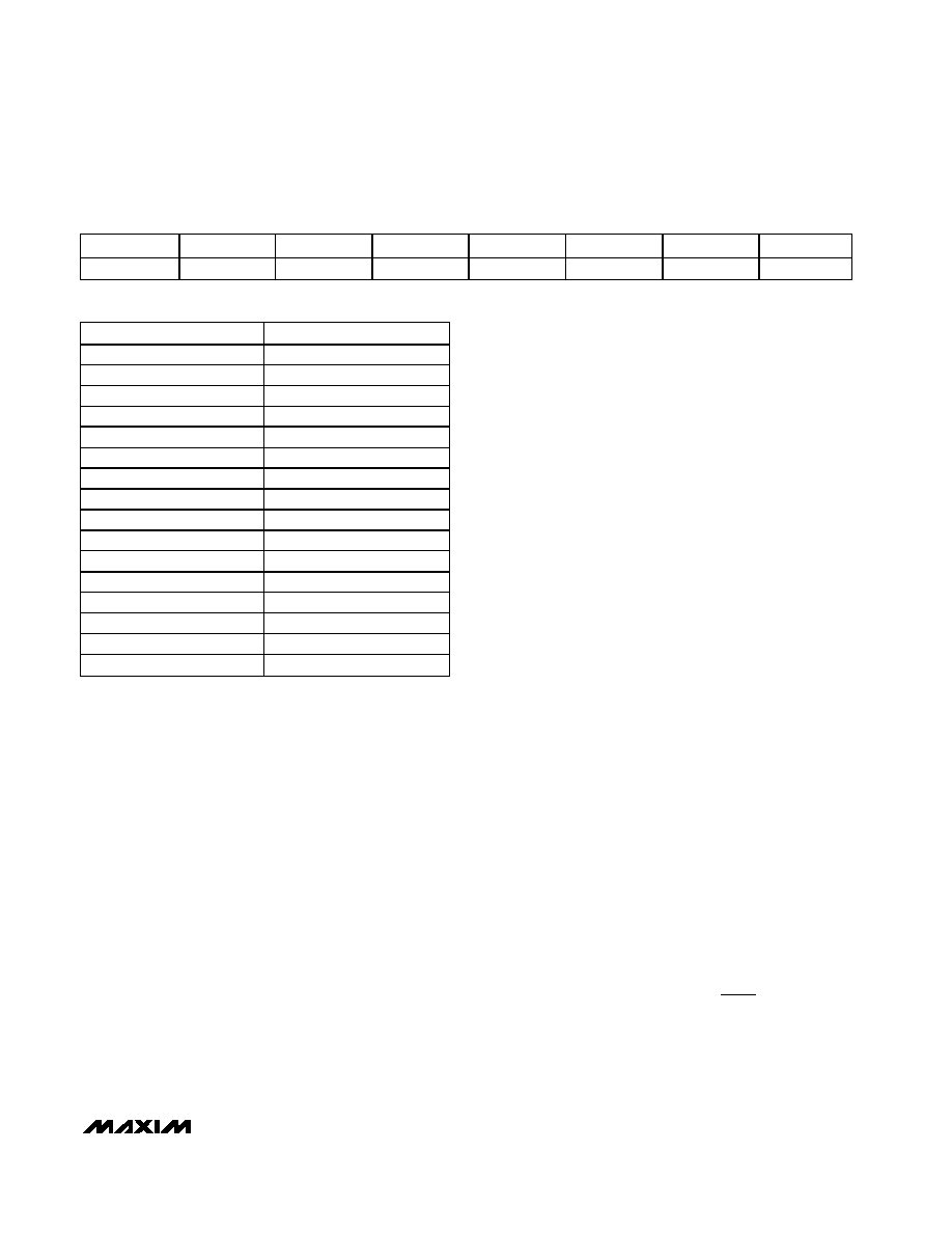
Table 13. Channel Configuration Register Format
B7 (MSB)
B6
B5
B4
B3
B2
B1
B0 (LSB)
Fault B3
Fault B2
Fault B1
Fault B0
Ave B3
Ave B2
Ave B1
Ave B0
Table 14. Conversion Average Encoding
CODE
N
0000
1, no averaging
0001
2
0010
4
0011
8
0100
16
0101
32
0110
64
0111
128
1000
256
1001
512
1010
1024
1011
2048
1100
Reserved
1101
Reserved
1110
Reserved
1111
Reserved
相关PDF资料 |
PDF描述 |
|---|---|
| VE-2TF-IW-F4 | CONVERTER MOD DC/DC 72V 100W |
| XRT83D10IW-F | IC LIU T1/E1 SGL 28SOJ |
| VI-J1Z-MW-F1 | CONVERTER MOD DC/DC 2V 40W |
| 206039-1 | CONN PLUG CPC 28POS REV SER 2 |
| 211769-3 | CONN RCPT CPC 9POS REV FREE HANG |
相关代理商/技术参数 |
参数描述 |
|---|---|
| MAX1254BEUE+ | 功能描述:模数转换器 - ADC 12-Bit 10Ch 94ksps 5V Precision ADC RoHS:否 制造商:Texas Instruments 通道数量:2 结构:Sigma-Delta 转换速率:125 SPs to 8 KSPs 分辨率:24 bit 输入类型:Differential 信噪比:107 dB 接口类型:SPI 工作电源电压:1.7 V to 3.6 V, 2.7 V to 5.25 V 最大工作温度:+ 85 C 安装风格:SMD/SMT 封装 / 箱体:VQFN-32 |
| MAX1254BEUE+T | 功能描述:模数转换器 - ADC 12-Bit 10Ch 94ksps 5V Precision ADC RoHS:否 制造商:Texas Instruments 通道数量:2 结构:Sigma-Delta 转换速率:125 SPs to 8 KSPs 分辨率:24 bit 输入类型:Differential 信噪比:107 dB 接口类型:SPI 工作电源电压:1.7 V to 3.6 V, 2.7 V to 5.25 V 最大工作温度:+ 85 C 安装风格:SMD/SMT 封装 / 箱体:VQFN-32 |
| MAX1254BEUE-T | 功能描述:模数转换器 - ADC RoHS:否 制造商:Texas Instruments 通道数量:2 结构:Sigma-Delta 转换速率:125 SPs to 8 KSPs 分辨率:24 bit 输入类型:Differential 信噪比:107 dB 接口类型:SPI 工作电源电压:1.7 V to 3.6 V, 2.7 V to 5.25 V 最大工作温度:+ 85 C 安装风格:SMD/SMT 封装 / 箱体:VQFN-32 |
| MAX1254EVC16 | 功能描述:模数转换器 - ADC Stand-Alone 10-Channel 12-Bit System Monitors with Internal Temperature Sensor and VDD Monitor RoHS:否 制造商:Texas Instruments 通道数量:2 结构:Sigma-Delta 转换速率:125 SPs to 8 KSPs 分辨率:24 bit 输入类型:Differential 信噪比:107 dB 接口类型:SPI 工作电源电压:1.7 V to 3.6 V, 2.7 V to 5.25 V 最大工作温度:+ 85 C 安装风格:SMD/SMT 封装 / 箱体:VQFN-32 |
| MAX1254EVKIT | 功能描述:数据转换 IC 开发工具 Evaluation Kit/Evaluation System for the MAX1254 MAX1253 RoHS:否 制造商:Texas Instruments 产品:Demonstration Kits 类型:ADC 工具用于评估:ADS130E08 接口类型:SPI 工作电源电压:- 6 V to + 6 V |
发布紧急采购,3分钟左右您将得到回复。