- 您现在的位置:买卖IC网 > PDF目录1935 > MAX13041ASD/V+T (Maxim Integrated Products)IC CAN TXRX +/-80V HS 14SOIC PDF资料下载
参数资料
| 型号: | MAX13041ASD/V+T |
| 厂商: | Maxim Integrated Products |
| 文件页数: | 3/20页 |
| 文件大小: | 0K |
| 描述: | IC CAN TXRX +/-80V HS 14SOIC |
| 产品培训模块: | Lead (SnPb) Finish for COTS Obsolescence Mitigation Program |
| 标准包装: | 2,500 |
| 类型: | 收发器 |
| 驱动器/接收器数: | 1/1 |
| 规程: | CAN |
| 电源电压: | 4.75 V ~ 5.25 V |
| 安装类型: | 表面贴装 |
| 封装/外壳: | 14-SOIC(0.154",3.90mm 宽) |
| 供应商设备封装: | 14-SOIC |
| 包装: | 带卷 (TR) |
Detailed Description
The MAX13041 ±80V fault-protected, high-speed CAN
transceiver is intended for high-speed industrial and
automotive network applications where high reliability
and advanced power management are required. The
device links a CAN protocol controller to the physical
bus wires of the controller area network (CAN) and
allows communication at speeds up to 1Mbps. Built-in
level shifting allows for direct connection to protocol con-
trollers operating from lower voltages. The extended
fault-protected voltage range of ±80V on CAN bus lines
allows for use in +12V or +42V automotive, and higher
voltage +24V and +36V heavy-duty truck applications.
Advanced power management features make the
MAX13041 ideal for automotive electronic control unit
(ECU) modules that are permanently supplied by bat-
tery, regardless of the ignition switch position (clamp-
30, type-A modules). The device controls one or more
external voltage regulators to provide a low-power
sleep mode for an entire clamp-30 node. Wake-on CAN
capability allows the MAX13041 to restore power to the
node upon detection of CAN bus activity. The
MAX13041 is functionally compatible with the Philips
TJA1041A and is a pin-to-pin replacement with
improved performance.
CAN Interface
The ISO11898 specification describes the physical
layer of a controller area network (CAN). A CAN imple-
mentation is comprised of multiple transceiver modules
linked by a pair of bus wires. Communication between
modules occurs through transmission and reception of
differential logic states on the bus lines. Two compli-
mentary logic states are defined by ISO11898. A domi-
nant state results when the differential voltage on the
CAN bus lines is greater than 0.9V. A recessive bus
state results when the differential voltage is less than
0.5V (Figure 1). The CAN bus exhibits a wired-AND
characteristic, meaning the bus is only recessive when
all connected transmitters are recessive. Any transmit-
ter asserting a dominant logic state forces the entire
CAN bus dominant.
The MAX13041 accepts logic-level data from the CAN
protocol controller on TXD. Drive TXD low to assert a
dominant state on the CAN bus. Drive TXD high to
release the CAN bus to a recessive state. TXD is inter-
nally pulled up to VI/O. The state of the CAN bus is pre-
sented to the protocol controller as a logic level on
RXD. The MAX13041 receiver remains active during
transmission to allow for the bit-wise arbitration scheme
specified by the CAN protocol.
Level Shifting
The MAX13041 provides level shifting on TXD, RXD,
EN,
STB, WAKE and ERR for compatibility with lower-
voltage protocol controllers. Set the interface logic lev-
els for TXD, RXD, EN,
STB, WAKE, and ERR by
connecting VI/O to the supply voltage of a CAN protocol
controller, or another voltage from +2.8V to +5.25V.
Split-Termination and Common-Mode
Voltage Stabilization
The CAN bus specification requires a total bus load resis-
tance of 60Ω. Each end of the bus should be terminated
with 120Ω, the characteristic impedance of the bus line.
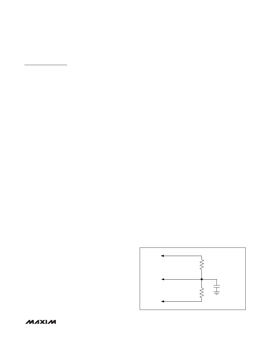
Electromagnetic emission (EME) is reduced by a split-ter-
mination method, whereby each end of the bus line is ter-
minated by 120Ω split into two 60Ω resistors in series
(see Figure 3). A bypass capacitor shunts noise to
ground from the node connecting the 60Ω resistors.
When the CAN bus is recessive, the common-mode
voltage is pulled low by the leakage current from inac-
tive modules. When the CAN bus subsequently goes
dominant, the proper common-mode voltage is
restored by the transmitting device. A common-mode
voltage step results, generating excessive EME. To mit-
igate this problem, the common-mode voltage of the
bus is forced to VCC/2 by biasing the split-termination
node (see Figure 3). During normal and PWON/listen-
only modes, a stabilized DC voltage of VCC/2 is present
on SPLIT. Connect SPLIT to the node connecting the
two 60Ω termination resistors to stabilize the common-
mode voltage of the bus and prevent EME from com-
mon-mode voltage steps.
Power-Management Operating Modes
The MAX13041 provides advanced power management
for a clamp-30 node by controlling one or more external
voltage regulators. Five operating modes provide differ-
ent functionality to minimize power consumption.
MAX13041
±80V Fault-Protected High-Speed CAN Transceiver
with Low-Power Management and Wake-On CAN
______________________________________________________________________________________
11
SPLIT
CANH
CANL
RT
60
Ω
CSPLIT
RT
60
Ω
Figure 3. Biased Split Termination
相关PDF资料 |
PDF描述 |
|---|---|
| MAX13051ASA+ | IC TRANSCEIVER CAN 8-SOIC |
| MAX13054ASA+T | IC TRANSCEIVER CAN HS 8-SOIC |
| MAX13087ECPA+ | IC TXRX RS485/422 5V ESD 8-DIP |
| MAX13174ECAG+ | IC CBL TERMINATION NETWRK 24SSOP |
| MAX13184EESD+ | IC TXRX RS-485 +5.0V ESD 14SOIC |
相关代理商/技术参数 |
参数描述 |
|---|---|
| MAX13042EEBC+ | 制造商:Maxim Integrated Products 功能描述: |
| MAX13042EEBC+T | 功能描述:转换 - 电压电平 4Ch 100Mbps 3.2V RoHS:否 制造商:Micrel 类型:CML/LVDS/LVPECL to LVCMOS/LVTTL 传播延迟时间:1.9 ns 电源电流:14 mA 电源电压-最大:3.6 V 电源电压-最小:3 V 最大工作温度:+ 85 C 安装风格:SMD/SMT 封装 / 箱体:MLF-8 |
| MAX13042EETD+ | 制造商:Maxim Integrated Products 功能描述:1.62V TO 3.6V IMPROVED HIGH-SPEED L - Rail/Tube |
| MAX13042EETD+T | 功能描述:转换 - 电压电平 4Ch 100Mbps 3.2V RoHS:否 制造商:Micrel 类型:CML/LVDS/LVPECL to LVCMOS/LVTTL 传播延迟时间:1.9 ns 电源电流:14 mA 电源电压-最大:3.6 V 电源电压-最小:3 V 最大工作温度:+ 85 C 安装风格:SMD/SMT 封装 / 箱体:MLF-8 |
| MAX13042EEVKIT+ | 功能描述:电源管理IC开发工具 MAX13042E Eval Kit RoHS:否 制造商:Maxim Integrated 产品:Evaluation Kits 类型:Battery Management 工具用于评估:MAX17710GB 输入电压: 输出电压:1.8 V |
发布紧急采购,3分钟左右您将得到回复。