- 您现在的位置:买卖IC网 > PDF目录20146 > MAX1366ECM+T (Maxim Integrated)IC PANEL METER 4.5 DIG 48LQFP PDF资料下载
参数资料
| 型号: | MAX1366ECM+T |
| 厂商: | Maxim Integrated |
| 文件页数: | 13/36页 |
| 文件大小: | 0K |
| 描述: | IC PANEL METER 4.5 DIG 48LQFP |
| 产品培训模块: | Lead (SnPb) Finish for COTS Obsolescence Mitigation Program |
| 标准包装: | 2,000 |
| 显示器类型: | LED |
| 配置: | 7 段显示 |
| 接口: | 串行 |
| 数字或字符: | A/D,4.5 位数字 |
| 电源电压: | 2.7 V ~ 5.25 V |
| 工作温度: | -40°C ~ 85°C |
| 安装类型: | 表面贴装 |
| 封装/外壳: | 48-LQFP |
| 供应商设备封装: | 48-LQFP(7x7) |
| 包装: | 带卷 (TR) |
第1页第2页第3页第4页第5页第6页第7页第8页第9页第10页第11页第12页当前第13页第14页第15页第16页第17页第18页第19页第20页第21页第22页第23页第24页第25页第26页第27页第28页第29页第30页第31页第32页第33页第34页第35页第36页
�� �
�
�Microcontroller-Interface,� 4.5-/3.5-Digit� Panel�
�Meters� with� 4–20mA� Output�
�Internal� Analog� Input/Reference� Buffers�
�The� MAX1366/MAX1368� analog� input/reference� buffers�
�allow� the� use� of� high-impedance� signal� sources.� The�
�input� buffers’� common-mode� input� range� allows� the� ana-�
�log� inputs� and� the� reference� to� range� from� -2.2V� to� +2.2V.�
�Modulator�
�The� MAX1366/MAX1368� perform� analog-to-digital� con-�
�versions� using� a� single-bit,� 3rd-order,� sigma-delta� mod-�
�ulator.� The� sigma-delta� modulator� converts� the� input�
�signal� into� a� digital� pulse� train� whose� average� duty�
�cycle� represents� the� digitized� signal� information.� The�
�modulator� quantizes� the� input� signal� at� a� much� higher�
�sample� rate� than� the� bandwidth� of� the� input.� The�
�0�
�-40�
�-80�
�-120�
�-160�
�-200�
�MAX1366/MAX1368� modulator� provides� 3rd-order� fre-�
�0�
�10�
�20�
�30�
�40�
�50�
�60�
�quency� shaping� of� the� quantization� noise� resulting� from�
�the� single-bit� quantizer.� The� modulator� is� fully� differen-�
�tial� for� maximum� signal-to-noise� ratio� and� minimum� sus-�
�ceptibility� to� power-supply� noise.� A� single-bit� data�
�stream� is� then� presented� to� the� digital� filter� to� remove�
�the� frequency-shaped� quantization� noise.�
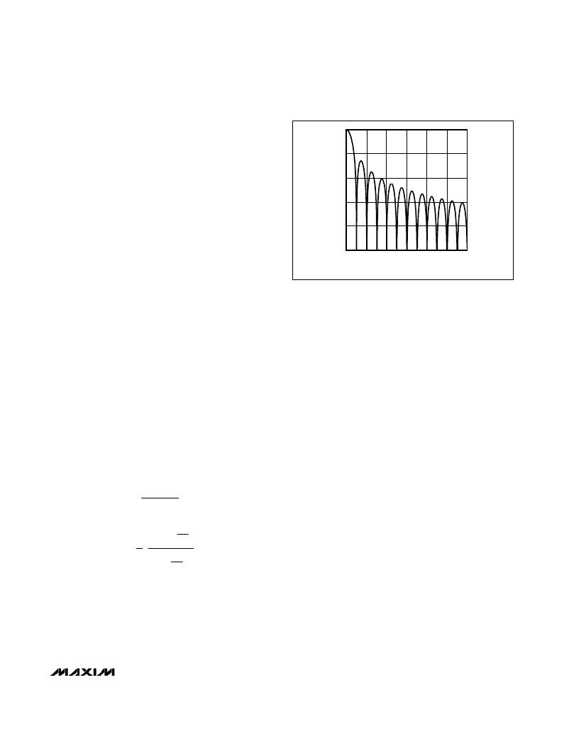
�Digital� Filtering�
�The� MAX1366/MAX1368� contain� an� on-chip� digital� low-�
�pass� filter� that� processes� the� data� stream� from� the�
�modulator� using� a� SINC� 4� response:�
�FREQUENCY� (Hz)�
�Figure� 1.� Frequency� Response� of� the� SINC� 4� Filter� (Notch� at� 60Hz)�
�ratio� (OSR)� for� the� MAX1368� is� 128� and� the� OSR� for� the�
�MAX1366� is� 1024.� The� output� data� rate� for� the� digital� fil-�
�ter� corresponds� to� the� positioning� of� the� first� notch� of�
�the� filter� ’s� frequency� response.� The� notches� of� the�
�SINC� 4� filter� are� repeated� at� multiples� of� the� first� notch�
�frequency.� The� SINC� 4� filter� provides� an� attenuation� of�
�?� sin(� x� )� ?�
�?�
�x� ?�
�?� ?�
�4�
�better� than� 100dB� at� these� notches.� For� example,� 50Hz�
�is� equal� to� 10� times� the� first� notch� frequency� and� 60Hz�
�is� equal� to� 12� times� the� first� notch� frequency.� For� large�
�step� changes� at� the� input,� allow� a� settling� time� of�
�The� SINC� 4� filter� has� a� settling� time� of� four� output� data�
�periods� (4� x� 200ms).� The� MAX1366/MAX1368� have�
�25%� overrange� capability� built� into� the� modulator� and�
�digital� filter.� The� digital� filter� is� optimized� for� the� f� CLK�
�equal� to� 4.9152MHz.� The� frequency� response� of� the�
�SINC� 4� filter� is� calculated� as� follows:�
�800ms� before� valid� data� is� read.�
�Clock� Modes�
�Configure� the� MAX1366/MAX1368� to� use� either� the�
�internal� oscillator� or� an� externally� applied� clock� to� drive�
�the� modulator,� filter,� and� DAC.� Set� the� EXTCLK� bit� in�
�the� control� register� to� zero� to� put� the� device� in� internal�
�?� 1� (� 1� ?� Z� ?� N� )� ?�
�?� N� (� 1� ?� Z� ?� 1� )� ?�
�f� m� ?� ?� ?�
�?� sin� ?� N� π� ?�
�H� (� f� )� =�
�?� sin� ?� π� f� ?� ?�
�?� ?�
�?� f� ?� ?�
�H� (� z� )� =� ?� ?�
�?� ?�
�?� ?� f� ?� ?�
�N� ?� ?�
�1� ?� ?�
�4�
�?� m� ?� ?�
�4�
�clock� mode.� Set� the� EXTCLK� bit� to� one� to� put� the�
�device� in� external� clock� mode.� When� using� the� internal�
�oscillator,� connect� CLK� to� GND� or� DV� DD� .� The�
�MAX1366/MAX1368� operate� with� a� 4.9152MHz� clock� to�
�achieve� maximum� rejection� of� 50Hz/60Hz� common-�
�mode,� power-supply,� and� normal-mode� noise.�
�Internal� Clock� Mode�
�The� MAX1366/MAX1368� contain� an� internal� oscillator.�
�The� power-up� condition� for� the� MAX1366/MAX1368� is�
�internal� clock� operation� with� the� EXTCLK� bit� in� the� con-�
�where� N� is� the� oversampling� ratio,� and� f� m� =� N� x� output�
�data� rate� =� 5Hz.�
�Filter� Characteristics�
�Figure� 1� shows� the� filter� frequency� response.� The�
�SINC� 4� characteristic� -3dB� cutoff� frequency� is� 0.228�
�times� the� first� notch� frequency� (5Hz).� The� oversampling�
�trol� register� equal� to� zero.� Using� the� internal� oscillator�
�saves� board� space� by� removing� the� need� for� an� exter-�
�nal� clock� source.�
�External-Clock� Mode�
�For� external� clock� operation,� set� the� EXTCLK� bit� in� the�
�control� register� to� one� and� drive� CLK� with� a� 4.9152MHz�
�______________________________________________________________________________________�
�13�
�相关PDF资料 |
PDF描述 |
|---|---|
| VI-22W-CX-F4 | CONVERTER MOD DC/DC 5.5V 75W |
| VI-22W-CX-F3 | CONVERTER MOD DC/DC 5.5V 75W |
| MAX7232BFIQH+D | IC DRVR DECODE 8DIG 44-PLCC |
| RCB92DHFT-S250 | EDGECARD PCI 184POS .050 5V SMD |
| VI-22W-CX-F2 | CONVERTER MOD DC/DC 5.5V 75W |
相关代理商/技术参数 |
参数描述 |
|---|---|
| MAX1366EVKIT | 功能描述:LED 照明开发工具 MAX1366 EVAL KIT RoHS:否 制造商:Fairchild Semiconductor 产品:Evaluation Kits 用于:FL7732 核心: 电源电压:120V 系列: 封装: |
| MAX1366EVKIT+ | 功能描述:LED 照明开发工具 MAX1366 Eval Kit RoHS:否 制造商:Fairchild Semiconductor 产品:Evaluation Kits 用于:FL7732 核心: 电源电压:120V 系列: 封装: |
| MAX1367ECM | 功能描述:LED显示驱动器 RoHS:否 制造商:Micrel 数位数量:5 片段数量: 安装风格:SMD/SMT 封装 / 箱体:PLCC-44 工作电源电压:4.75 V to 11 V 最大电源电流:10 mA 最大工作温度:+ 85 C 最小工作温度:- 40 C 封装:Tube |
| MAX1367ECM+ | 功能描述:LED显示驱动器 Stand-Alone 3.5Digit Panel Meters RoHS:否 制造商:Micrel 数位数量:5 片段数量: 安装风格:SMD/SMT 封装 / 箱体:PLCC-44 工作电源电压:4.75 V to 11 V 最大电源电流:10 mA 最大工作温度:+ 85 C 最小工作温度:- 40 C 封装:Tube |
| MAX1367ECM+T | 功能描述:LED显示驱动器 Stand-Alone 3.5Digit Panel Meters RoHS:否 制造商:Micrel 数位数量:5 片段数量: 安装风格:SMD/SMT 封装 / 箱体:PLCC-44 工作电源电压:4.75 V to 11 V 最大电源电流:10 mA 最大工作温度:+ 85 C 最小工作温度:- 40 C 封装:Tube |
发布紧急采购,3分钟左右您将得到回复。