参数资料
| 型号: | MAX1403CAI+T |
| 厂商: | Maxim Integrated Products |
| 文件页数: | 18/36页 |
| 文件大小: | 0K |
| 描述: | IC ADC 18BIT LP 28-SSOP |
| 产品培训模块: | Lead (SnPb) Finish for COTS Obsolescence Mitigation Program |
| 标准包装: | 2,000 |
| 位数: | 18 |
| 采样率(每秒): | 480 |
| 数据接口: | QSPI?,串行,SPI? |
| 转换器数目: | 1 |
| 功率耗散(最大): | 21.45mW |
| 电压电源: | 模拟和数字 |
| 工作温度: | 0°C ~ 70°C |
| 安装类型: | 表面贴装 |
| 封装/外壳: | 28-SSOP(0.209",5.30mm 宽) |
| 供应商设备封装: | 28-SSOP |
| 包装: | 带卷 (TR) |
| 输入数目和类型: | 3 个差分,单极;3 个差分,双极;5 个伪差分,单极;5 个伪差分,双极 |
第1页第2页第3页第4页第5页第6页第7页第8页第9页第10页第11页第12页第13页第14页第15页第16页第17页当前第18页第19页第20页第21页第22页第23页第24页第25页第26页第27页第28页第29页第30页第31页第32页第33页第34页第35页第36页
MAX1403
+3V, 18-Bit, Low-Power, Multichannel,
Oversampling (Sigma-Delta) ADC
______________________________________________________________________________________
25
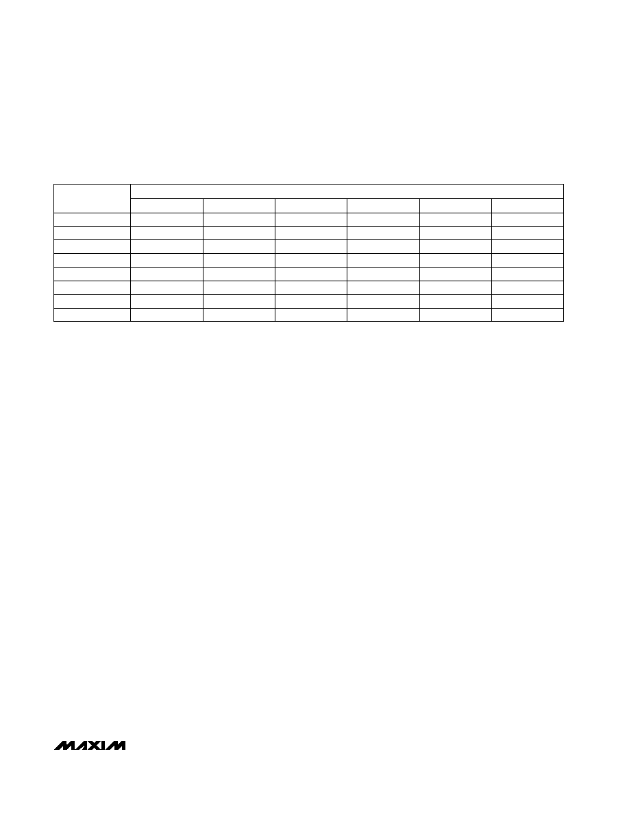
Table 14. REXT, CEXT Values for Less than 16-Bit Gain Error in Buffered (BUFF = 1)
Mode—All Modulator Sampling Frequencies (MF1, MF0 = XX); X2CLK = 0; CLKIN =
2.4576MHz
10
2
10
4
1
CEXT = 0pF
CEXT = 50pF
CEXT = 100pF
10
PGA GAIN
10
CEXT = 500pF
CEXT = 1000pF
CEXT = 5000pF
EXTERNAL RESISTANCE, REXT (k
)
10
16
10
32
8
10
64
10
128
10
Reference Input
The MAX1403 is optimized for ratiometric measure-
ments and includes a fully differential reference input.
Apply the reference voltage across REFIN+ and REFIN-,
ensuring that REFIN+ is more positive than REFIN-.
REFIN+ and REFIN- must be between AGND and V+.
The MAX1403 is specified with a +1.25V reference.
Modulator
The MAX1403 performs analog-to-digital conversion
using a single-bit, second-order, switched-capacitor
modulator. A single comparator within the modulator
quantizes the input signal at a much higher sample rate
than the bandwidth of the signal to be converted. The
quantizer then presents a stream of 1s and 0s to the
digital filter for processing, to remove the frequency-
shaped quantization noise.
The MAX1403 modulator provides 2nd-order frequency
shaping of the quantization noise resulting from the sin-
gle bit quantizer. The modulator is fully differential for
maximum signal-to-noise ratio and minimum suscepti-
bility to power-supply noise.
The modulator operates at one of a total of eight differ-
ent sampling rates (fM) determined by the master clock
frequency (fCLKIN), the X2CLK bit, the CLK bit, and the
modulator frequency control bits MF1 and MF0. Power
dissipation is optimized for each of these modes by
controlling the bias level of the modulator. Table 15
shows the input and reference sample rates.
PGA
A programmable gain amplifier (PGA) with a user-
selectable gain of x1, x2, x4, x8, x16, x32, x64, or x128
(Table 6) precedes the modulator. Figure 8 shows the
default bipolar transfer function with the following illus-
trated codes: 1) PGA = 0, DAC = 0; 2) PGA = 3, DAC =
0; or 3) PGA = 3, DAC = 3.
Output Noise
Tables 16a and 16b show the rms noise for typical out-
put frequencies (notches) and -3dB frequencies for the
MAX1403 with fCLKIN = 2.4576MHz. The numbers
given are for the bipolar input ranges with VREF =
+1.25V, with no buffer (BUFF = 0), and with the buffer
inserted (BUFF = 1). These numbers are typical and
are generated at a differential analog input voltage of 0.
Figure 7 shows graphs of Effective Resolution vs. Gain
and Notch Frequency. The effective resolution values
were derived from the following equation:
Effective Resolution = (SNRdB - 1.76dB) / 6.02
The maximum possible signal divided by the noise of
the device, SNRdB, is defined as the ratio of the input
full-scale voltage (i.e., 2 VREFIN / GAIN) to the output
rms noise. Note that it is not calculated using peak-to-
peak output noise numbers. Peak-to-peak noise num-
bers can be up to 6.6 times the rms numbers, while
effective resolution numbers based on peak-to-peak
noise can be 2.5 bits below the effective resolution
based on rms noise, as quoted in the tables.
The noise shown in Tables 16a and 16b is composed
of device noise and quantization noise. The device
noise is relatively low, but becomes the limiting noise
source for high gain settings. The quantization noise is
dependent on the notch frequency and becomes the
dominant noise source as the notch frequency is
increased.
相关PDF资料 |
PDF描述 |
|---|---|
| MS3122E10-6PW | CONN RCPT 6POS BOX MNT W/PINS |
| MAX166AEWP+ | IC ADC 8BIT MPU COMP 20-SOIC |
| MS27497E14F37P | CONN RCPT 37POS WALL MNT W/PINS |
| MX7821KR+T | IC ADC 8BIT T/H 20-SOIC |
| MS27656P9A35PA | CONN RCPT 6POS WALL MNT W/PINS |
相关代理商/技术参数 |
参数描述 |
|---|---|
| MAX1403EAI | 功能描述:模数转换器 - ADC RoHS:否 制造商:Texas Instruments 通道数量:2 结构:Sigma-Delta 转换速率:125 SPs to 8 KSPs 分辨率:24 bit 输入类型:Differential 信噪比:107 dB 接口类型:SPI 工作电源电压:1.7 V to 3.6 V, 2.7 V to 5.25 V 最大工作温度:+ 85 C 安装风格:SMD/SMT 封装 / 箱体:VQFN-32 |
| MAX1403EAI+ | 功能描述:模数转换器 - ADC 18-Bit 5Ch 4.8ksps 1.25V Precision ADC RoHS:否 制造商:Texas Instruments 通道数量:2 结构:Sigma-Delta 转换速率:125 SPs to 8 KSPs 分辨率:24 bit 输入类型:Differential 信噪比:107 dB 接口类型:SPI 工作电源电压:1.7 V to 3.6 V, 2.7 V to 5.25 V 最大工作温度:+ 85 C 安装风格:SMD/SMT 封装 / 箱体:VQFN-32 |
| MAX1403EAI+T | 功能描述:模数转换器 - ADC 18-Bit 5Ch 4.8ksps 1.25V Precision ADC RoHS:否 制造商:Texas Instruments 通道数量:2 结构:Sigma-Delta 转换速率:125 SPs to 8 KSPs 分辨率:24 bit 输入类型:Differential 信噪比:107 dB 接口类型:SPI 工作电源电压:1.7 V to 3.6 V, 2.7 V to 5.25 V 最大工作温度:+ 85 C 安装风格:SMD/SMT 封装 / 箱体:VQFN-32 |
| MAX1403EAI-T | 功能描述:模数转换器 - ADC RoHS:否 制造商:Texas Instruments 通道数量:2 结构:Sigma-Delta 转换速率:125 SPs to 8 KSPs 分辨率:24 bit 输入类型:Differential 信噪比:107 dB 接口类型:SPI 工作电源电压:1.7 V to 3.6 V, 2.7 V to 5.25 V 最大工作温度:+ 85 C 安装风格:SMD/SMT 封装 / 箱体:VQFN-32 |
| MAX1403EVKIT | 功能描述:数据转换 IC 开发工具 MAX1403 Eval Kit RoHS:否 制造商:Texas Instruments 产品:Demonstration Kits 类型:ADC 工具用于评估:ADS130E08 接口类型:SPI 工作电源电压:- 6 V to + 6 V |
发布紧急采购,3分钟左右您将得到回复。