- 您现在的位置:买卖IC网 > PDF目录1936 > MAX14502AETL+T (Maxim Integrated Products)IC CARD READER USB-SD 40-TQFN PDF资料下载
参数资料
| 型号: | MAX14502AETL+T |
| 厂商: | Maxim Integrated Products |
| 文件页数: | 16/41页 |
| 文件大小: | 0K |
| 描述: | IC CARD READER USB-SD 40-TQFN |
| 产品培训模块: | Lead (SnPb) Finish for COTS Obsolescence Mitigation Program |
| 标准包装: | 2,500 |
| 应用: | USB |
| 接口: | I²C,2 线串口 |
| 电源电压: | 1.8 V ~ 3.3 V |
| 封装/外壳: | 40-WFQFN 裸露焊盘 |
| 供应商设备封装: | 40-TQFN-EP(5x5) |
| 包装: | 带卷 (TR) |
| 安装类型: | 表面贴装 |
第1页第2页第3页第4页第5页第6页第7页第8页第9页第10页第11页第12页第13页第14页第15页当前第16页第17页第18页第19页第20页第21页第22页第23页第24页第25页第26页第27页第28页第29页第30页第31页第32页第33页第34页第35页第36页第37页第38页第39页第40页第41页
MAX14500–MAX14503
Hi-Speed USB-to-SD Card
Readers with Bypass
______________________________________________________________________________________
23
Control Register (0x00)
The control register controls the settings of SD port
analog switches, Card Reader mode, and sleep (Table
2.) The state of the SD port analog switches can be
changed when the device is in Sleep mode or in Card
Reader mode, and actions are executed immediately. If
SD card 1 is connected to the PC through USB in Card
Reader mode, the state of the SD port 1 switches are
ignored, but the SD port 2 switches can still be con-
trolled through the Control register. Likewise, if SD card
2 is connected to the USB connector in Card Reader
mode, the state of the SD port 2 switches are ignored,
but the SD port 1 switches can still be controlled
through the Control register. Changing the card reader
bits in Sleep mode does not cause the device to enter
Card Reader mode. Under this condition, the
MAX14500–MAX14503 enter Card Reader mode upon
waking up.
Configuration Registers
The MAX14500–MAX14503 have three configuration reg-
isters (CONFIG1 = 0x01, CONFIG2 = 0x02, CONFIG3 =
0x03). The configuration registers control the SD bus
bit data mode, interrupt polarity, interrupt clearance,
clock configuration, SD clock, and USB speed for Card
Reader mode. The default settings are shown in the
Register Map section.
Interrupts (INT)
All interrupts are masked in the default reset state.
There are two interrupt enable registers (IE1 = 0x04, IE2
= 0x05) and two interrupt request registers (IRQ1 =
0x10, IRQ2 = 0x11). The BERR/INT output functions as
the bridge error output BERR in simple control and func-
tions as an interrupt INT in I2C control. The polarity of
INT and how INT is asserted can be programmed in
CONFIG1. The INT output asserts for enabled interrupts
and errors in Card Reader mode. The polarity of INT can
be active-high or active-low, and INT can be pro-
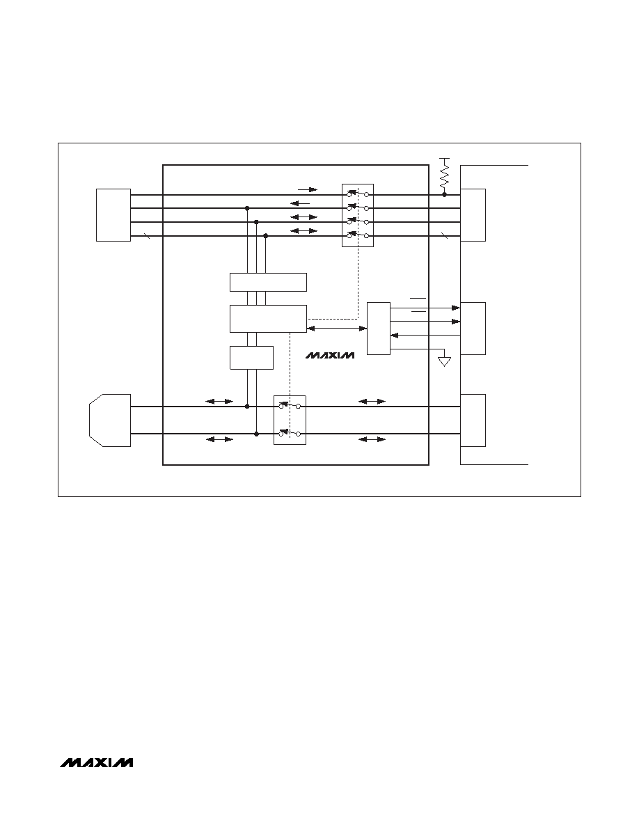
HCRD_PRST
HCLK1
HCMD1
HDAT1_[3:0]
CD+
HOST PROCESSOR
USB SWITCHES
CD-
D+
D-
HD+
HD-
USB
CONNECTOR
SD CARD INTERFACE
USB HS
CARD READER
CCRD_PRST
SD PORT 1 SWITCHES
CCLK1
CCMD1
BUSY
BERR
MODE = LOW
4
CDAT1_[3:0]
I2C_SEL = LOW
SD
PORT1
I/O
LEVEL
TRANSLATORS
HOST
I/O
SD
SLOT 1
USB
TRANSCEIVER
MAX14500–
MAX14503
Figure 10. I2C_SEL Connected Low to Enable Simple Control and MODE = 0 to Enable Pass Thru
相关PDF资料 |
PDF描述 |
|---|---|
| MAX14505EWC+T | IC SWITCH DUAL SPDT 12WLP |
| MAX14523BATA/V+T | IC CURRENT LIMIT SWITCH 8TDFN |
| MAX1452AAE+T | IC SENSOR SIGNAL COND 16-SSOP |
| MAX14531EEWC+T | IC USB SWITCH DP3T 12WLP |
| MAX14536EEVB+ | IC SWITCH DPDT 10UTQFN |
相关代理商/技术参数 |
参数描述 |
|---|---|
| MAX14502EVKIT+ | 功能描述:界面开发工具 MAX14502 Eval Kit RoHS:否 制造商:Bourns 产品:Evaluation Boards 类型:RS-485 工具用于评估:ADM3485E 接口类型:RS-485 工作电源电压:3.3 V |
| MAX14503AEWN+ | 制造商:Maxim Integrated Products 功能描述: |
| MAX14503ETL+ | 制造商:Maxim Integrated Products 功能描述: |
| MAX14504EWC+T | 功能描述:模拟开关 IC Dual SPDT Neg Rail w/ +/-VCC Cap RoHS:否 制造商:Texas Instruments 开关数量:2 开关配置:SPDT 开启电阻(最大值):0.1 Ohms 切换电压(最大): 开启时间(最大值): 关闭时间(最大值): 工作电源电压:2.7 V to 4.5 V 最大工作温度:+ 85 C 安装风格:SMD/SMT 封装 / 箱体:DSBGA-16 |
| MAX14505AEWC+ | 制造商:Maxim Integrated Products 功能描述:DUAL SPDT NEGATIVE RAIL ANALOG SWIT - Rail/Tube |
发布紧急采购,3分钟左右您将得到回复。