- 您现在的位置:买卖IC网 > PDF目录1936 > MAX14502AETL+T (Maxim Integrated Products)IC CARD READER USB-SD 40-TQFN PDF资料下载
参数资料
| 型号: | MAX14502AETL+T |
| 厂商: | Maxim Integrated Products |
| 文件页数: | 20/41页 |
| 文件大小: | 0K |
| 描述: | IC CARD READER USB-SD 40-TQFN |
| 产品培训模块: | Lead (SnPb) Finish for COTS Obsolescence Mitigation Program |
| 标准包装: | 2,500 |
| 应用: | USB |
| 接口: | I²C,2 线串口 |
| 电源电压: | 1.8 V ~ 3.3 V |
| 封装/外壳: | 40-WFQFN 裸露焊盘 |
| 供应商设备封装: | 40-TQFN-EP(5x5) |
| 包装: | 带卷 (TR) |
| 安装类型: | 表面贴装 |
第1页第2页第3页第4页第5页第6页第7页第8页第9页第10页第11页第12页第13页第14页第15页第16页第17页第18页第19页当前第20页第21页第22页第23页第24页第25页第26页第27页第28页第29页第30页第31页第32页第33页第34页第35页第36页第37页第38页第39页第40页第41页
MAX14500–MAX14503
Hi-Speed USB-to-SD Card
Readers with Bypass
______________________________________________________________________________________
27
sists of two blocks: a clock squarer input (enabled by
default), which accepts low-signal amplitude TCXO sig-
nals (down to 200mV), and a PLL with fixed dividers.
The PLL sub system can be configured using the I2C
interface. The complete list of PLL subsystem combina-
tions are listed in Table 3.
I2C Serial Interface
Serial Addressing
The MAX14500–MAX14503 operate as I2C slave devices
that send and receive data through an I2C-compatible
2-wire interface. The interface uses a serial-data line
(SDA) and a serial-clock line (SCL) to achieve bidirec-
tional communication between master(s) and slave(s). A
master initiates all data transfers to and from the
MAX14500–MAX14503, and generates the SCL clock
that synchronizes the data transfer. The SDA line oper-
ates as both an input and an open-drain output requiring
a pullup resistor on SDA. The SCL line operates only as
an input. A pullup resistor is required on SCL if there are
multiple masters on the 2-wire interface, or if the master
in a single-master system has an open-drain SCL output.
Each transmission consists of a START (S) condition by
a master, followed by the MAX14500–MAX14503’s 7-bit
slave address, plus a R/W bit, a register address byte,
one or more data bytes, and finally a STOP (P) condition.
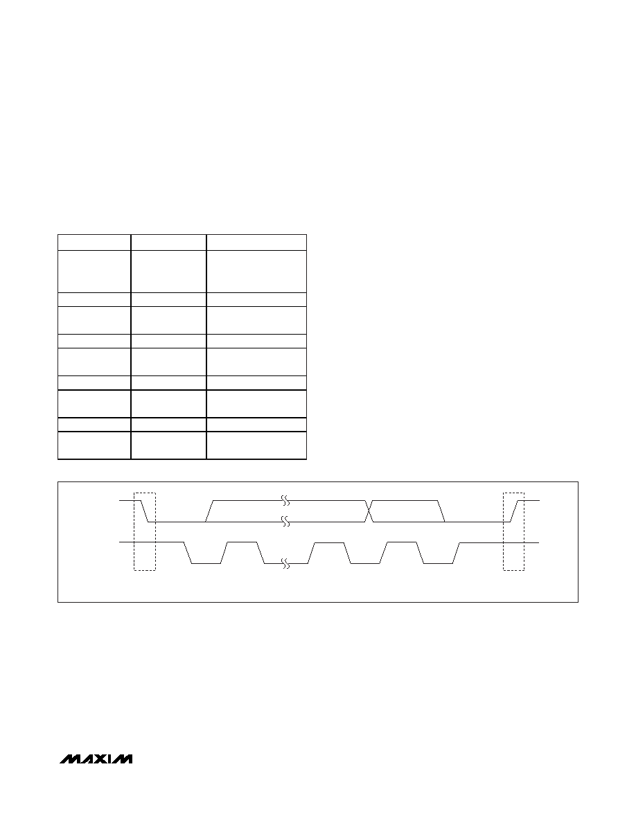
START and STOP Conditions
Both SCL and SDA remain high when the interface is
idle. A master signals the beginning of a transmission
with a START condition by transitioning SDA from high
to low while SCL is high (Figure 13). When the master
has finished communicating with the slave, it issues a
STOP condition by transitioning SDA from low to high
while SCL is high. The bus is then free for another
transmission.
CLKSOURCE
SOURCE (MHz)
NOTES
00000b
See Ordering
Information/
Selector Guide
Default low-amplitude
clock
00001b
19.2
Rail-to-rail square wave
00010b
19.2
Low-amplitude sine
wave
00101b
13.0
Rail-to-rail square wave
00110b
13.0
Low-amplitude sine
wave
01001b
12.0
Rail-to-rail square wave
01010b
12.0
Low-amplitude sine
wave
01101b
26.0
Rail-to-rail square wave
01110b
26.0
Low-amplitude sine
wave
Table 3. Clock Source Bit Values
SDA
SCL
START
CONDITION
STOP
CONDITION
S
P
Figure 13. START and STOP Conditions
相关PDF资料 |
PDF描述 |
|---|---|
| MAX14505EWC+T | IC SWITCH DUAL SPDT 12WLP |
| MAX14523BATA/V+T | IC CURRENT LIMIT SWITCH 8TDFN |
| MAX1452AAE+T | IC SENSOR SIGNAL COND 16-SSOP |
| MAX14531EEWC+T | IC USB SWITCH DP3T 12WLP |
| MAX14536EEVB+ | IC SWITCH DPDT 10UTQFN |
相关代理商/技术参数 |
参数描述 |
|---|---|
| MAX14502EVKIT+ | 功能描述:界面开发工具 MAX14502 Eval Kit RoHS:否 制造商:Bourns 产品:Evaluation Boards 类型:RS-485 工具用于评估:ADM3485E 接口类型:RS-485 工作电源电压:3.3 V |
| MAX14503AEWN+ | 制造商:Maxim Integrated Products 功能描述: |
| MAX14503ETL+ | 制造商:Maxim Integrated Products 功能描述: |
| MAX14504EWC+T | 功能描述:模拟开关 IC Dual SPDT Neg Rail w/ +/-VCC Cap RoHS:否 制造商:Texas Instruments 开关数量:2 开关配置:SPDT 开启电阻(最大值):0.1 Ohms 切换电压(最大): 开启时间(最大值): 关闭时间(最大值): 工作电源电压:2.7 V to 4.5 V 最大工作温度:+ 85 C 安装风格:SMD/SMT 封装 / 箱体:DSBGA-16 |
| MAX14505AEWC+ | 制造商:Maxim Integrated Products 功能描述:DUAL SPDT NEGATIVE RAIL ANALOG SWIT - Rail/Tube |
发布紧急采购,3分钟左右您将得到回复。