- 您现在的位置:买卖IC网 > PDF目录11652 > MAX1455AUE+ (Maxim Integrated Products)IC AUTO SNSR SIGNAL COND 16TSSOP PDF资料下载
参数资料
| 型号: | MAX1455AUE+ |
| 厂商: | Maxim Integrated Products |
| 文件页数: | 5/25页 |
| 文件大小: | 0K |
| 描述: | IC AUTO SNSR SIGNAL COND 16TSSOP |
| 产品培训模块: | Lead (SnPb) Finish for COTS Obsolescence Mitigation Program |
| 标准包装: | 96 |
| 类型: | 自动 |
| 输入类型: | 模拟 |
| 输出类型: | 模拟 |
| 电流 - 电源: | 6mA |
| 安装类型: | 表面贴装 |
| 封装/外壳: | 16-TSSOP(0.173",4.40mm 宽) |
| 供应商设备封装: | 16-TSSOP |
| 包装: | 管件 |
Serial Digital Output
DIO is configured as a digital output by writing a Read
IRS (RDIRS) command (5 hex) to the CRIL location. On
receipt of this command, the MAX1455 outputs a byte
of data, the contents of which are determined by the
IRS pointer (IRSP[3:0]) value at location IRSA[3:0] =
8hex. The data is output as a single byte, framed by a
start bit and a stop bit. Table 11 lists the data returned
for each IRSP address value.
Once the RDIRS command has been sent, all connec-
tions to DIO must be three-stated to allow the MAX1455
to drive the DIO line. Following receipt of the RDIRS
command, the MAX1455 drives DIO high after 1 byte
time. The MAX1455 holds DIO high for a single bit time
and then asserts a start bit (drives DIO low). The start
bit is then followed by the data byte and a stop bit.
Immediately following transmission of the stop bit, the
MAX1455 three-states DIO, releasing the line. The
MAX1455 is then ready to receive the next command
sequence 1 byte time after release of DIO.
Note that there are time intervals before and after the
MAX1455 sends the data byte when all devices on the
DIO line are three-stated. It is recommended that a
weak pullup resistor be applied to the DIO line during
these time intervals to prevent unwanted transitions
(Figure 4). In applications where DIO and analog out-
put (OUT) are not connected, a pullup resistor should
be permanently connected to DIO. If the MAX1455 DIO
and analog outputs are connected, then do not load
this common line during analog measurements. In this
situation, perform the following sequence:
1) Connect a pullup resistor to the DIO/OUT line,
preferably with a relay.
2) Send the RDIRS command.
3) Three-state the user connection (set to high imped-
ance).
4) Receive data from the MAX1455.
5) Activate the user connection (pull DIO/OUT line high).
6) Release the pullup resistor.
MAX1455
Low-Cost Automotive Sensor Signal
Conditioner
______________________________________________________________________________________
13
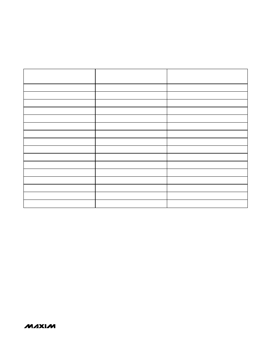
IRO SIGN, IRO[2:0]
INPUT-REFERRED OFFSET
CORRECTION AS % OF VDD
INPUT-REFERRED OFFSET, CORRECTION
AT VDD = 5VDC IN mV
1,111
+1.25
+63
1,110
+1.08
+54
1,101
+0.90
+45
1,100
+0.72
+36
1,011
+0.54
+27
1,010
+0.36
+18
1,001
+0.18
+9
1,000
0
0,000
0
0,001
-0.18
-9
0,010
-0.36
-18
0,011
-0.54
-27
0,100
-0.72
-36
0,101
-0.90
-45
0,110
-1.08
-54
0,111
-1.25
-63
Table 7. Input Referred Offset (IRO[2:0])
相关PDF资料 |
PDF描述 |
|---|---|
| MCF51AC256ACLKE | MCU 32BIT 256K FLASH CAN 80-LQFP |
| MC908AP32CFBE | IC MCU 32K FLASH 8MHZ 44QFP |
| 221185-1 | CONN PLUG BNC 75 OHM DUAL CRIMP |
| PCF51JM128EVLK | MCU 32BIT 128K FLASH 80-LQFP |
| VI-JN4-IZ-B1 | CONVERTER MOD DC/DC 48V 25W |
相关代理商/技术参数 |
参数描述 |
|---|---|
| MAX1455AUE+ | 功能描述:板上安装温度传感器 Automotive Sensor Signal Conditioner RoHS:否 制造商:Omron Electronics 输出类型:Digital 配置: 准确性:+/- 1.5 C, +/- 3 C 温度阈值: 数字输出 - 总线接口:2-Wire, I2C, SMBus 电源电压-最大:5.5 V 电源电压-最小:4.5 V 最大工作温度:+ 50 C 最小工作温度:0 C 关闭: 安装风格: 封装 / 箱体: 设备功能:Temperature and Humidity Sensor |
| MAX1455AUE+T | 功能描述:板上安装温度传感器 Automotive Sensor Signal Conditioner RoHS:否 制造商:Omron Electronics 输出类型:Digital 配置: 准确性:+/- 1.5 C, +/- 3 C 温度阈值: 数字输出 - 总线接口:2-Wire, I2C, SMBus 电源电压-最大:5.5 V 电源电压-最小:4.5 V 最大工作温度:+ 50 C 最小工作温度:0 C 关闭: 安装风格: 封装 / 箱体: 设备功能:Temperature and Humidity Sensor |
| MAX1455AUE-T | 功能描述:板上安装温度传感器 Automotive Sensor Signal Conditioner RoHS:否 制造商:Omron Electronics 输出类型:Digital 配置: 准确性:+/- 1.5 C, +/- 3 C 温度阈值: 数字输出 - 总线接口:2-Wire, I2C, SMBus 电源电压-最大:5.5 V 电源电压-最小:4.5 V 最大工作温度:+ 50 C 最小工作温度:0 C 关闭: 安装风格: 封装 / 箱体: 设备功能:Temperature and Humidity Sensor |
| MAX1455C/D | 功能描述:板上安装温度传感器 RoHS:否 制造商:Omron Electronics 输出类型:Digital 配置: 准确性:+/- 1.5 C, +/- 3 C 温度阈值: 数字输出 - 总线接口:2-Wire, I2C, SMBus 电源电压-最大:5.5 V 电源电压-最小:4.5 V 最大工作温度:+ 50 C 最小工作温度:0 C 关闭: 安装风格: 封装 / 箱体: 设备功能:Temperature and Humidity Sensor |
| MAX1455C/D DIE | 制造商:Maxim Integrated Products 功能描述: |
发布紧急采购,3分钟左右您将得到回复。