- 您现在的位置:买卖IC网 > PDF目录296460 > MAX16005DUE+ (MAXIM INTEGRATED PRODUCTS INC) 6-CHANNEL POWER SUPPLY MANAGEMENT CKT, PDSO16 PDF资料下载
参数资料
| 型号: | MAX16005DUE+ |
| 厂商: | MAXIM INTEGRATED PRODUCTS INC |
| 元件分类: | 电源管理 |
| 英文描述: | 6-CHANNEL POWER SUPPLY MANAGEMENT CKT, PDSO16 |
| 封装: | 5 X 4.40 MM, ROHS COMPLIANT, TSSOP-16 |
| 文件页数: | 24/26页 |
| 文件大小: | 280K |
| 代理商: | MAX16005DUE+ |
MAX16000–MAX16007
Low-Voltage, Quad-/Hex-/Octal-Voltage
P Supervisors
_______________________________________________________________________________________
7
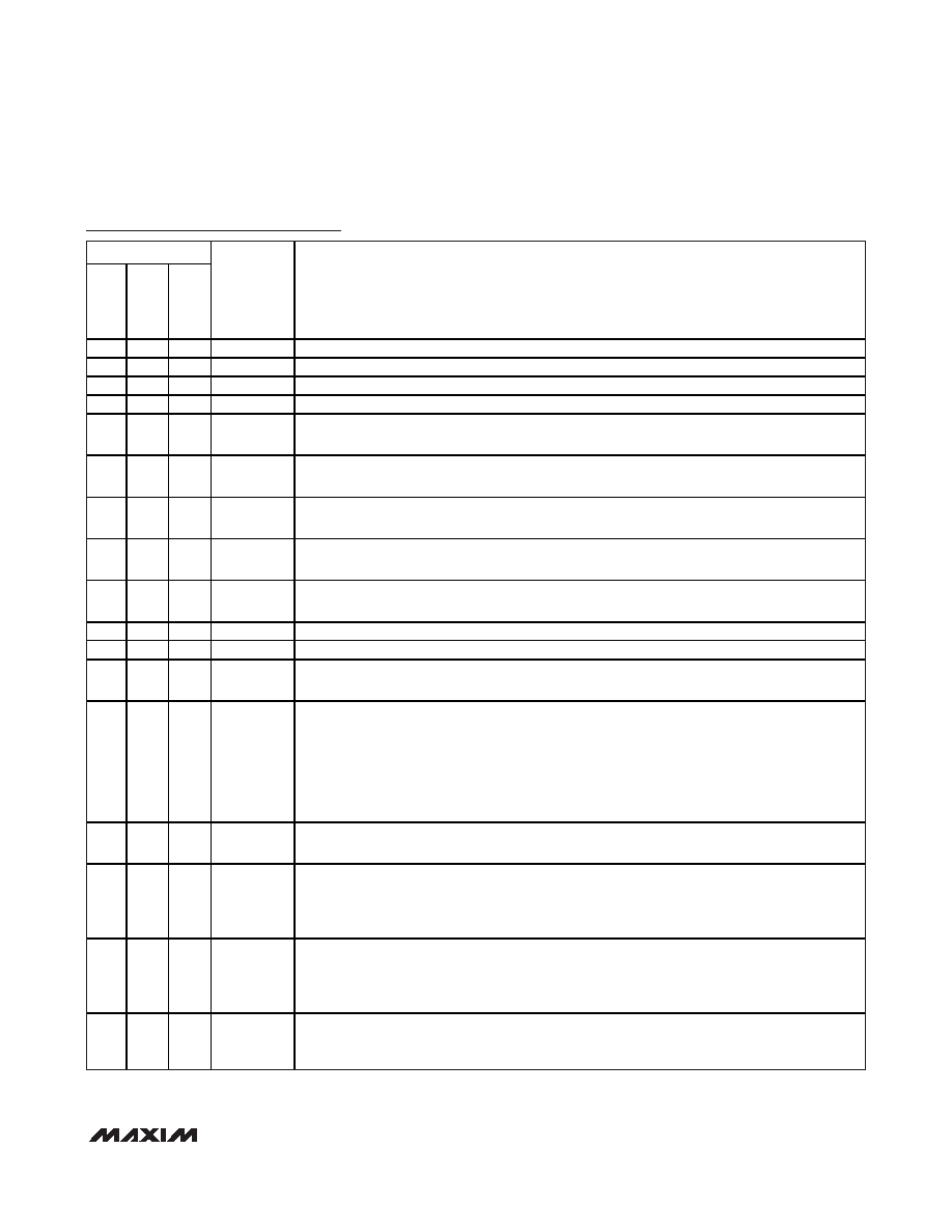
Pin Description (MAX16000/MAX16001/MAX16002)
PIN
MAX16000
MAX16001
MAX16002
NAME
FUNCTION
1
IN3
Monitored Input Voltage 3. See Table 1 for the input voltage threshold.
2
IN4
Monitored Input Voltage 4. See Table 1 for the input voltage threshold.
3
4
GND
Ground
45
5
VCC
Unmonitored Power-Supply Input
5
6
—
OUT3
Output 3. When the voltage at IN3 falls below its threshold, OUT3 goes low and stays low until the
voltage at IN3 exceeds its threshold. The open-drain output has a 30A internal pullup to VCC.
6
7
—
OUT4
Output 4. When the voltage at IN4 falls below its threshold, OUT4 goes low and stays low until the
voltage at IN4 exceeds its threshold. The open-drain output has a 30A internal pullup to VCC.
710
8
MARGIN
Active-Low Manual Deassert Input. Pull MARGIN low to deassert all outputs (go into high state),
regardless of the voltage at any monitored input.
8
11
—
OUT2
Output 2. When the voltage at IN2 falls below its threshold, OUT2 goes low and stays low until the
voltage at IN2 exceeds its threshold. The open-drain output has a 30A internal pullup to VCC.
9
12
—
OUT1
Output 1. When the voltage at IN1 falls below its threshold, OUT1 goes low and stays low until the
voltage at IN1 exceeds its threshold. The open-drain output has a 30A internal pullup to VCC.
10
14
10
IN1
Monitored Input Voltage 1. See Table 1 for the input voltage threshold.
11
15
11
IN2
Monitored Input Voltage 2. See Table 1 for the input voltage threshold.
12
16
12
TOL
Threshold Tolerance Input. Connect TOL to GND to select 5% threshold tolerance. Connect TOL
to VCC to select 10% threshold tolerance.
—
3
WDI
Watchdog Timer Input. If WDI remains low or high for longer than the watchdog timeout period,
RESET is asserted. The timer clears whenever a reset is asserted or a rising or falling edge on
WDI is detected. The watchdog timer enters a startup period that allows 54s for the first
transition to occur before a reset. Leave WDI unconnected to disable the watchdog timer. The
WDI open-state detector uses a small 400nA current. Therefore, do not connect WDI to anything
that will source or sink more than 200nA. Note that the leakage current specification for most
three-state drivers exceeds 200nA.
—8
6
MR
Active-Low Manual Reset Input. Pull MR low to assert RESET low. RESET remains low for the
reset timeout period after MR is deasserted. MR is pulled up to VCC through a 20k
resistor.
—
9
7
SRT
Set Reset Timeout Input. Connect a capacitor from SRT to GND to set the reset timeout period.
The reset timeout period can be calculated as follows:
Reset Timeout (s) = 2.06 x 10⁶ (
) x CSRT (F). For the internal timeout period of 140ms (min),
connect SRT to VCC.
—13
9
RESET
Active-Low Reset Output. RESET asserts low when any of the monitored voltages falls below its
respective threshold or MR is asserted. RESET remains asserted for the reset timeout period
after all monitored voltages exceed their respective thresholds and MR is deasserted. This
open-drain output has a 30A internal pullup.
——
—
EP
Exposed Pad. EP is internally connected to GND. Connect EP to the ground plane to provide a
low thermal resistance path from the IC junction to the PCB. Do not use as the electrical
connection to GND.
相关PDF资料 |
PDF描述 |
|---|---|
| MAX16072RS30D3+ | POWER SUPPLY SUPPORT CKT, PBGA4 |
| MAX17004AETJ+ | 3.3 A DUAL SWITCHING CONTROLLER, 575 kHz SWITCHING FREQ-MAX, QCC32 |
| MAX177ENG | CMOS 10-Bit A/D Converter with Track-and-Hold |
| MAX207EEAG | 5V High-Speed RS-232 Transceivers with 0.1uF Capacitors |
| MAX207ENG | 5V High-Speed RS-232 Transceivers with 0.1uF Capacitors |
相关代理商/技术参数 |
参数描述 |
|---|---|
| MAX16005ETE+ | 功能描述:监控电路 Quad/Hex/Octal Volt uP Supervisor RoHS:否 制造商:STMicroelectronics 监测电压数: 监测电压: 欠电压阈值: 过电压阈值: 输出类型:Active Low, Open Drain 人工复位:Resettable 监视器:No Watchdog 电池备用开关:No Backup 上电复位延迟(典型值):10 s 电源电压-最大:5.5 V 最大工作温度:+ 85 C 安装风格:SMD/SMT 封装 / 箱体:UDFN-6 封装:Reel |
| MAX16005ETE+T | 功能描述:监控电路 Quad/Hex/Octal Volt uP Supervisor RoHS:否 制造商:STMicroelectronics 监测电压数: 监测电压: 欠电压阈值: 过电压阈值: 输出类型:Active Low, Open Drain 人工复位:Resettable 监视器:No Watchdog 电池备用开关:No Backup 上电复位延迟(典型值):10 s 电源电压-最大:5.5 V 最大工作温度:+ 85 C 安装风格:SMD/SMT 封装 / 箱体:UDFN-6 封装:Reel |
| MAX16005EUE+ | 制造商:Maxim Integrated Products 功能描述: |
| MAX16006ATG | 制造商:Maxim Integrated Products 功能描述:LOW-VOLTAGE, QUAD-/HEX-/OCTAL-VOLTAGE MICROPR - Rail/Tube |
| MAX16006ATG+ | 功能描述:监控电路 Quad/Hex/Octal Volt uP Supervisor RoHS:否 制造商:STMicroelectronics 监测电压数: 监测电压: 欠电压阈值: 过电压阈值: 输出类型:Active Low, Open Drain 人工复位:Resettable 监视器:No Watchdog 电池备用开关:No Backup 上电复位延迟(典型值):10 s 电源电压-最大:5.5 V 最大工作温度:+ 85 C 安装风格:SMD/SMT 封装 / 箱体:UDFN-6 封装:Reel |
发布紧急采购,3分钟左右您将得到回复。