- 您现在的位置:买卖IC网 > PDF目录20753 > MAX17149ETE+T (Maxim Integrated)IC LED DRVR 6CH STEP UP 16QFN PDF资料下载
参数资料
| 型号: | MAX17149ETE+T |
| 厂商: | Maxim Integrated |
| 文件页数: | 15/21页 |
| 文件大小: | 0K |
| 描述: | IC LED DRVR 6CH STEP UP 16QFN |
| 标准包装: | 2,500 |
| 系列: | Quick-PWM™ |
| 拓扑: | 开路漏极,PWM,升压(升压) |
| 输出数: | 6 |
| 内部驱动器: | 是 |
| 类型 - 主要: | 车载,背光 |
| 类型 - 次要: | 白色 LED |
| 频率: | 可调节/可选择 |
| 电源电压: | 3 V ~ 26 V |
| 安装类型: | 表面贴装 |
| 封装/外壳: | 16-WFQFN 裸露焊盘 |
| 供应商设备封装: | 16-TQFN(3x3) |
| 包装: | 带卷 (TR) |
| 工作温度: | -40°C ~ 85°C |
�� �
�
�Low-Cost,� 6-String� WLED� Drivers� with�
�Quick-PWM� Step-Up� Converter�
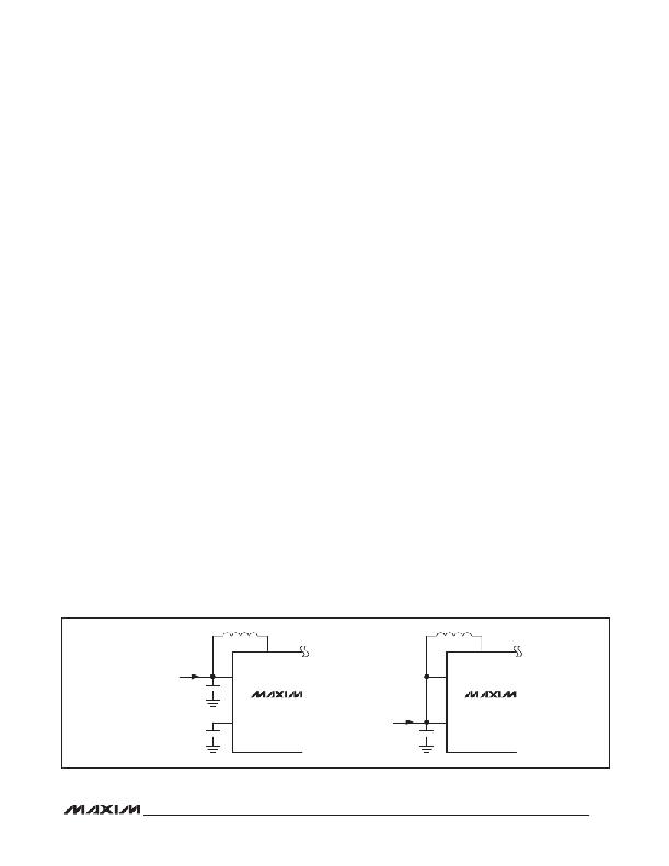
�Figure� 5� shows� possible� supply� connection� configura-�
�tions� for� the� devices.� The� V� CC� pin� should� be� bypassed�
�to� GND� with� a� minimum� 1� F� F� ceramic� capacitor.�
�Startup�
�At� startup,� the� devices� perform� an� LED� check� by� pull-�
�ing� up� each� FB_� pin� with� a� current� source� to� determine�
�whether� a� string� of� LEDs� are� connected.� If� an� FB_� pin�
�is� not� connected� with� LEDs,� it� is� disabled.� The� process�
�takes� approximately� 1ms.� Then� the� current� sources� are�
�turned� on.�
�Shutdown�
�The� devices� can� be� placed� into� shutdown� by� pulling� the�
�EN� pin� low;� when� in� shutdown� mode,� the� current� con-�
�sumption� is� 5� F� A� max.� In� the� devices,� the� V� CC� voltage�
�drops� to� 0V� with� EN� low.�
�Overvoltage� Protection�
�To� protect� the� step-up� regulator� when� the� load� is� open,�
�or� the� output� voltage� becomes� excessive� for� any� rea-�
�son,� the� devices� feature� a� dedicated� overvoltage� feed-�
�back� input� by� monitoring� output� (OVP).� There� are� two�
�thresholds� for� OVP� and� they� provide� careful� protections.�
�When� the� OVP� voltage� exceeds� the� 43V� (typ)� for� the�
�MAX17129� or� 25.4V� for� the� MAX17149,� an� overvoltage�
�flag� is� set� to� enable� the� open-string� detection.� When�
�the� OVP� voltage� exceeds� 45.2V� (typ),� the� internal� power�
�MOSFET� stops� switching.� This� step-up� regulator� switch�
�is� reenabled� after� the� V� OVP� drops� 1.8V� (typ� hysteresis)�
�below� the� protection� threshold.� This� overvoltage� protec-�
�tion� feature� ensures� the� step-up� regulator� fail-safe� opera-�
�tion� when� the� LED� strings� are� disconnected� from� the�
�output.� Considering� overvoltage� threshold� and� minimum�
�output� regulation� voltage,� the� MAX17149� is� suitable� for�
�3–6� LEDs� per� string� and� the� MAX17129� is� suitable� for�
�6–11� LEDs� per� string.�
�LX�
�Overcurrent� Protection�
�When� in� overcurrent� condition,� the� devices� latch� off� after�
�a� fault� timer� expires.� If� running� at� full� brightness,� the�
�timeout� is� approximately� 0.8ms� (typ).� If� dimming,� this�
�timeout� is� dependent� on� the� dimming� frequency� and�
�duty� cycle:� the� sum� of� the� on-time� cycles,� during� which�
�the� device� is� in� overcurrent� condition,� must� be� 0.8ms�
�(typ)� for� the� timeout� to� expire.�
�LED� Current� Sources�
�Maintaining� uniform� LED� brightness� and� dimming� capa-�
�bility� is� critical� for� backlight� applications.� The� ICs� are�
�equipped� with� a� bank� of� six� matched� current� sources.�
�These� specialized� current� sources� are� accurate� within�
�Q� 3%� and� match� with� each� other� within� 2%.� The� LED�
�full-scale� current� is� set� through� the� ISET� pin� (10mA� <�
�I� LED_FS� <� 45mA).�
�The� minimum� voltage� drop� across� each� current� source�
�is� 275mV� (typ)� when� the� LED� current� is� 20mA.� The� low-�
�voltage� drop� helps� reduce� dissipation� while� maintaining�
�sufficient� compliance� to� control� the� LED� current� within�
�the� required� tolerances.�
�The� LED� current� sources� can� be� disabled� by� connecting�
�the� respective� FB_� pin� to� GND� before� startup.� When� the�
�devices� are� enabled,� the� controller� scans� settings� for�
�all� FB_� pins.� If� a� FB_� pin� is� not� tied� to� GND,� an� internal�
�circuit� pulls� this� pin� high,� and� the� controller� enables� the�
�corresponding� current� source� to� regulate� the� string� cur-�
�rent.� If� the� FB_� pin� is� tied� to� GND,� the� controller� disables�
�the� corresponding� current� regulator.� The� current� regula-�
�tor� cannot� be� disabled� by� connecting� the� respective� FB_�
�pin� to� GND� after� the� IC� is� enabled.�
�All� FB_� pins� in� use� are� combined� to� extract� a� lowest� FB_�
�voltage� (LVC)� (see� Figure� 2).� LVC� is� fed� into� the� step-up�
�regulator’s� error� amplifier� and� is� used� to� set� the� output�
�voltage.�
�LX�
�V� IN�
�6V� TO� 26V�
�IN�
�IN�
�V� CC�
�MAX17129�
�MAX17149�
�V� S�
�3.0V� TO� 5.5V�
�V� CC�
�MAX17129�
�MAX17149�
�Figure� 5.� Supply� Configurations� for� the� MAX17129/MAX17149�
�15�
�相关PDF资料 |
PDF描述 |
|---|---|
| ABB66DHHD-S578 | EDGECARD 132POS .050 SLD W/POSTS |
| TPSD337M004R0045 | CAP TANT 330UF 4V 20% 2917 |
| HSC40DRYN-S13 | CONN EDGECARD 80POS .100 EXTEND |
| HSC40DRYH-S13 | CONN EDGECARD 80POS .100 EXTEND |
| TPSD337K010H0100 | CAP TANT 330UF 10V 10% 2917 |
相关代理商/技术参数 |
参数描述 |
|---|---|
| MAX1714AEEP | 功能描述:电流型 PWM 控制器 RoHS:否 制造商:Texas Instruments 开关频率:27 KHz 上升时间: 下降时间: 工作电源电压:6 V to 15 V 工作电源电流:1.5 mA 输出端数量:1 最大工作温度:+ 105 C 安装风格:SMD/SMT 封装 / 箱体:TSSOP-14 |
| MAX1714AEEP+ | 功能描述:电流型 PWM 控制器 Step-Down Controller for Notebook RoHS:否 制造商:Texas Instruments 开关频率:27 KHz 上升时间: 下降时间: 工作电源电压:6 V to 15 V 工作电源电流:1.5 mA 输出端数量:1 最大工作温度:+ 105 C 安装风格:SMD/SMT 封装 / 箱体:TSSOP-14 |
| MAX1714AEEP+T | 功能描述:电流型 PWM 控制器 Step-Down Controller for Notebook RoHS:否 制造商:Texas Instruments 开关频率:27 KHz 上升时间: 下降时间: 工作电源电压:6 V to 15 V 工作电源电流:1.5 mA 输出端数量:1 最大工作温度:+ 105 C 安装风格:SMD/SMT 封装 / 箱体:TSSOP-14 |
| MAX1714AEEP-T | 功能描述:电流型 PWM 控制器 RoHS:否 制造商:Texas Instruments 开关频率:27 KHz 上升时间: 下降时间: 工作电源电压:6 V to 15 V 工作电源电流:1.5 mA 输出端数量:1 最大工作温度:+ 105 C 安装风格:SMD/SMT 封装 / 箱体:TSSOP-14 |
| MAX1714AEEP-TG068 | 制造商:Rochester Electronics LLC 功能描述: 制造商:Maxim Integrated Products 功能描述: |
发布紧急采购,3分钟左右您将得到回复。