- 您现在的位置:买卖IC网 > PDF目录5055 > MAX1820XEUB+ (Maxim Integrated Products)IC REG BUCK WCDMA 10-MSOP PDF资料下载
参数资料
| 型号: | MAX1820XEUB+ |
| 厂商: | Maxim Integrated Products |
| 文件页数: | 11/18页 |
| 文件大小: | 0K |
| 描述: | IC REG BUCK WCDMA 10-MSOP |
| 产品培训模块: | Lead (SnPb) Finish for COTS Obsolescence Mitigation Program |
| 标准包装: | 50 |
| 应用: | 转换器,WCDMA 功率放大器应用 |
| 输入电压: | 2.6 V ~ 5.5 V |
| 输出数: | 1 |
| 输出电压: | 0.4 V ~ 3.4 V |
| 工作温度: | -40°C ~ 85°C |
| 安装类型: | 表面贴装 |
| 封装/外壳: | 10-TFSOP,10-MSOP(0.118",3.00mm 宽) |
| 供应商设备封装: | 10-µMAX |
| 包装: | 管件 |
��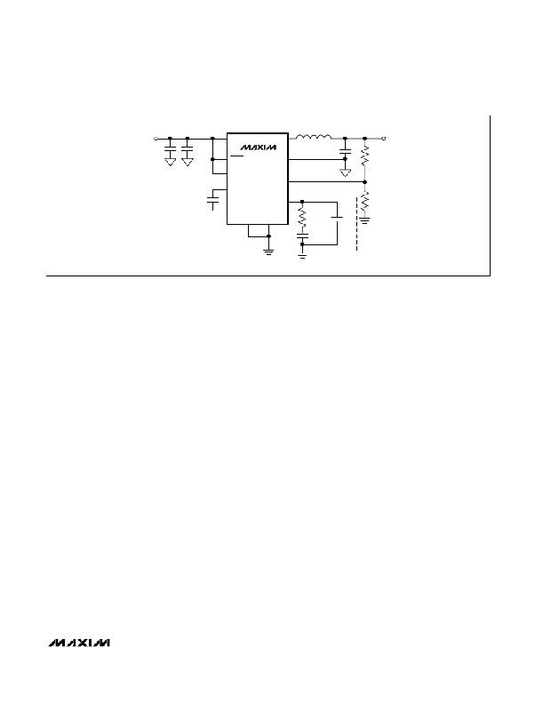 �
�
�WCDMA� Cellular� Phone� 600mA�
�Buck� Regulators�
�V� IN� =� 2.6V� TO� 5.5V�
�BATT�
�LX�
�4.7� μ� H�
�V� OUT� =� 1.5V�
�10� μ� F�
�0.1� μ� F�
�SHDN�
�MAX1821�
�PGND�
�4.7� μ� F�
�R1�
�6k� ?�
�SYNC�
�FB�
�REF�
�0.047� μ� F�
�COMP�
�R2�
�30k� ?�
�SKIP�
�GND�
�R� C�
�82k� ?�
�C1�
�C2*�
�1pF�
�330pF�
�*� CAN� BE� OMITTED� IF� CERAMIC� OUTPUT� CAPACITOR� IS� USED.�
�Figure� 3.� Standard� Operating� Circuit�
�the� load.� The� duty� cycle� of� a� buck� step-down� converter�
�is� ideally� a� ratio� of� the� output� voltage� to� input� voltage� in�
�steady-state� condition.�
�The� MAX1820/MAX1821� have� internal� switch� current�
�limits� of� 1.2A� (typ).� If� I� LX� exceeds� this� maximum,� the�
�high-side� FET� turns� off� and� the� synchronous� rectifier�
�turns� on.� This� lowers� the� duty� cycle� and� causes� the� out-�
�put� voltage� to� droop� as� long� as� the� load� current�
�remains� excessive.� There� is� also� a� synchronous� rectifier�
�current� limit� of� -0.85A� when� the� device� is� operating� in�
�forced� PWM� mode� (see� the� Forced� PWM� Operation� sec-�
�tion).� If� the� negative� current� limit� is� exceeded,� the� syn-�
�chronus� rectifier� is� turned� off,� and� the� inductor� current�
�continues� to� flow� through� its� body� diode� until� the� begin-�
�ning� of� the� next� cycle� or� the� inductor� current� drops� to�
�zero.� This� means� there� is� a� limit� on� how� much� current�
�the� device� is� allowed� to� shuttle� in� response� to� output�
�power� reduction.�
�Normal� Mode� Operation�
�Connecting� SKIP� to� GND� enables� MAX1820/MAX1821�
�normal� operation� (Figure� 3).� This� allows� automatic� PWM�
�control� at� medium� and� heavy� loads� and� skip� mode� at�
�light� loads� to� improve� efficiency� and� reduce� quiescent�
�current� to� 180μA.� Operating� in� normal� mode� also� allows�
�the� MAX1820/MAX1821� to� pulse� skip� when� the� peak�
�inductor� current� drops� below� 130mA,� corresponding� to�
�a� load� current� of� approximately� 65mA.�
�During� skip� operation,� the� MAX1820/MAX1821� switch�
�only� as� needed� to� service� the� load,� reducing� the�
�switching� frequency� and� associated� losses� in� the� inter-�
�nal� switch,� the� synchronous� rectifier,� and� the� external�
�inductor.�
�There� are� three� steady-state� operating� conditions� for�
�the� MAX1820/MAX1821� in� normal� mode.� The� device�
�performs� in� continuous� conduction� for� heavy� loads� in� a�
�manner� identical� to� forced� PWM� mode.� The� inductor�
�current� becomes� discontinuous� at� medium� loads,�
�requiring� the� synchronous� rectifier� to� be� turned� off�
�before� the� end� of� a� cycle� as� the� inductor� current� reach-�
�es� zero.� The� device� enters� into� skip� mode� when� the�
�converter� output� voltage� exceeds� its� regulation� limit�
�before� the� inductor� current� reaches� its� skip� thres-�
�hold� level.�
�During� skip� mode,� a� switching� cycle� initiates� when� the�
�output� voltage� has� dropped� out� of� regulation.� The� P-�
�channel� MOSFET� switch� turns� on� and� conducts� current�
�to� the� output-filter� capacitor� and� load� until� the� inductor�
�current� reaches� the� skip� peak� current� limit.� Then� the�
�main� switch� turns� off,� and� the� magnetic� field� in� the�
�inductor� collapses,� while� current� flows� through� the� syn-�
�chronous� rectifier� to� the� output� filter� capacitor� and� the�
�load.� The� synchronous� rectifier� is� turned� off� when� the�
�inductor� current� reaches� zero.� The� MAX1820/� MAX1821�
�wait� until� the� skip� comparator� senses� a� low� output� volt-�
�age� again.�
�Forced� PWM� Operation�
�Connect� SKIP� to� BATT� for� forced� PWM� operation.�
�Forced� PWM� operation� is� desirable� in� sensitive� RF� and�
�data-acquisition� applications� to� ensure� that� switching�
�harmonics� do� not� interfere� with� sensitive� IF� and� data-�
�sampling� frequencies.� A� minimum� load� is� not� required�
�during� forced� PWM� operation� since� the� synchronous�
�rectifier� passes� reverse-inductor� current� as� needed� to�
�allow� constant-frequency� operation� with� no� load.�
�______________________________________________________________________________________�
�11�
�相关PDF资料 |
PDF描述 |
|---|---|
| EBA40DTKT | CONN EDGECARD 80POS DIP .125 SLD |
| P1330-223K | INDUCTOR POWER 22.0UH SMD |
| X5649S14-2.7 | IC SUPERVISOR CPU 64K EE 14-SOIC |
| EEV-HD1E470P | CAP ALUM 47UF 25V 20% SMD |
| ECA43DTKN | CONN EDGECARD 86POS DIP .125 SLD |
相关代理商/技术参数 |
参数描述 |
|---|---|
| MAX1820XEUB+ | 功能描述:直流/直流开关调节器 WCDMA 600mA Buck Regulator RoHS:否 制造商:International Rectifier 最大输入电压:21 V 开关频率:1.5 MHz 输出电压:0.5 V to 0.86 V 输出电流:4 A 输出端数量: 最大工作温度: 安装风格:SMD/SMT 封装 / 箱体:PQFN 4 x 5 |
| MAX1820XEUB+T | 功能描述:直流/直流开关调节器 WCDMA 600mA Buck Regulator RoHS:否 制造商:International Rectifier 最大输入电压:21 V 开关频率:1.5 MHz 输出电压:0.5 V to 0.86 V 输出电流:4 A 输出端数量: 最大工作温度: 安装风格:SMD/SMT 封装 / 箱体:PQFN 4 x 5 |
| MAX1820XEUB-T | 功能描述:直流/直流开关调节器 RoHS:否 制造商:International Rectifier 最大输入电压:21 V 开关频率:1.5 MHz 输出电压:0.5 V to 0.86 V 输出电流:4 A 输出端数量: 最大工作温度: 安装风格:SMD/SMT 封装 / 箱体:PQFN 4 x 5 |
| MAX1820YEBC | 制造商:Maxim Integrated Products 功能描述:WCDMA CELLULAR PHONE 600MA BUCK REG - Rail/Tube |
| MAX1820YEBC+ | 制造商:Maxim Integrated Products 功能描述:CONV DC-DC SGL-OUT STEP DOWN 12UCSP - Rail/Tube |
发布紧急采购,3分钟左右您将得到回复。