- 您现在的位置:买卖IC网 > PDF目录15488 > MAX1875EEG+ (Maxim Integrated Products)IC REG CTRLR BUCK PWM VM 24-QSOP PDF资料下载
参数资料
| 型号: | MAX1875EEG+ |
| 厂商: | Maxim Integrated Products |
| 文件页数: | 11/21页 |
| 文件大小: | 0K |
| 描述: | IC REG CTRLR BUCK PWM VM 24-QSOP |
| 产品培训模块: | Lead (SnPb) Finish for COTS Obsolescence Mitigation Program |
| 标准包装: | 50 |
| PWM 型: | 电压模式 |
| 输出数: | 2 |
| 频率 - 最大: | 660kHz |
| 占空比: | 90% |
| 电源电压: | 4.75 V ~ 23 V |
| 降压: | 是 |
| 升压: | 无 |
| 回扫: | 无 |
| 反相: | 无 |
| 倍增器: | 无 |
| 除法器: | 无 |
| Cuk: | 无 |
| 隔离: | 无 |
| 工作温度: | -40°C ~ 85°C |
| 封装/外壳: | 24-SSOP(0.154",3.90mm 宽) |
| 包装: | 管件 |
�� �
�
�Dual� 180°� Out-of-Phase� PWM� Step-�
�Down� Controllers� with� POR�
�MAX1875/MAX1876� support� the� following� three� operat-�
�V� L�
�INPUT�
�(V� IN� )�
�ing� modes:�
�?� SYNC� =� GND:� The� CKO� output� frequency� equals�
�REG1� ’� s� switching� frequency� (f� CKO� =� f� DH1� )� and� the�
�CKO� signal� is� in� phase� with� REG1� ’� s� switching� fre-�
�MAX1875�
�BST_�
�DH_�
�LX_�
�5� ?�
�quency.� This� provides� 2-phase� operation� when� syn-�
�chronized� with� a� second� slave� controller.�
�?� SYNC� =� VL:� The� CKO� output� frequency� equals� two�
�times� REG1� ’� s� switching� frequency� (f� CKO� =� 2f� DH1� )�
�and� the� CKO� signal� is� phase� shifted� by� 90� °� with�
�respect� to� REG1� ’� s� switching� frequency.� This� pro-�
�vides� 4-phase� operation� when� synchronized� with� a�
�second� MAX1875/MAX1876� (slave� controller).�
�?� SYNC� Driven� by� External� Oscillator:� The� controller�
�generates� the� clock� signal� by� dividing� down� the�
�SYNC� input� signal,� so� that� the� switching� frequency�
�equals� half� the� synchronization� frequency� (f� SW� =�
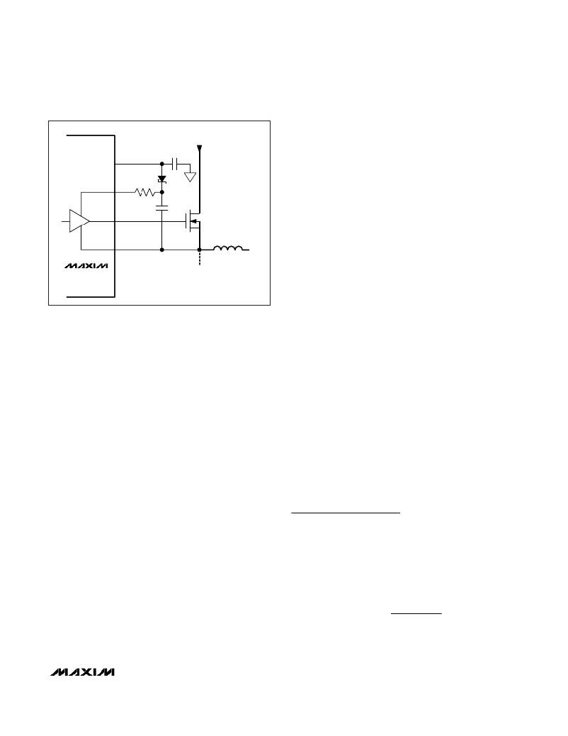
�Figure� 3.� Reducing� the� Switching-Node� Rise� Time�
�On� the� rising� edge� of� EN� both� controllers� enter� soft-�
�start.� Soft-start� gradually� ramps� up� to� the� reference�
�voltage� seen� by� the� error� amplifier� in� order� to� control�
�the� outputs� ’� rate� of� rise� and� reduce� input� surge� cur-�
�rents� during� startup.� The� soft-start� period� is� 1024� clock�
�cycles� (1024/f� SW� ),� and� the� internal� soft-start� DAC�
�ramps� up� the� voltage� in� 64� steps.� The� output� reaches�
�regulation� when� soft-start� is� completed.� On� the� falling�
�edge� of� EN� both� controllers� simultaneously� enter� soft-�
�stop,� which� reverses� the� soft-start� ramp.� The� part�
�enters� shutdown� after� soft-stop� is� complete.�
�Reset� Output� (MAX1876� Only)�
�RST� is� an� open-drain� output.� RST� pulls� low� when� either�
�output� falls� below� 90%� of� its� nominal� regulation� voltage.�
�Once� both� outputs� exceed� 90%� of� their� nominal� regulation�
�voltages� and� both� soft-start� cycles� are� completed,� RST�
�goes� high� impedance.� To� obtain� a� logic-voltage� output,�
�connect� a� pullup� resistor� from� RST� to� the� logic� supply� volt-�
�age.� A� 100k� ?� resistor� works� well� for� most� applications.� If�
�unused,� leave� RST� grounded� or� unconnected.�
�Clock� Synchronization� (SYNC,� CKO)�
�SYNC� serves� two� functions:� SYNC� selects� the� clock�
�output� (CKO)� type� used� to� synchronize� slave� con-�
�trollers,� or� it� serves� as� a� clock� input� so� the�
�MAX1875/MAX1876� can� be� synchronized� with� an� exter-�
�f� SYNC� /2).� REG1� ’� s� conversion� cycles� initiate� on� the� ris-�
�ing� edge� of� the� internal� clock� signal.� The� CKO� output�
�frequency� and� phase� match� REG1� ’� s� switching� fre-�
�quency� (f� CKO� =� f� DH1� )� and� the� CKO� signal� is� in�
�phase.� Note� that� the� MAX1875/MAX1876� still� require�
�R� OSC� when� SYNC� is� externally� clocked� and� the� inter-�
�nal� oscillator� frequency� should� be� set� to� 50%� of� the�
�synchronization� frequency� (f� OSC� =� 0.5� f� SYNC� ).�
�Thermal� Overload� Protection�
�Thermal� overload� protection� limits� total� power� dissipation�
�in� the� MAX1875/MAX1876.� When� the� device� ’� s� die-junc-�
�tion� temperature� exceeds� T� J� =� +160� °� C,� an� on-chip� ther-�
�mal� sensor� shuts� down� the� device,� forcing� DL_� and� DH_�
�low,� allowing� the� IC� to� cool.� The� thermal� sensor� turns� the�
�part� on� again� after� the� junction� temperature� cools� by�
�10� °� C.� During� thermal� shutdown,� the� regulators� shut�
�down,� RST� goes� low,� and� soft-start� is� reset.� If� the� V� L� lin-�
�ear-regulator� output� is� short-circuited,� thermal-overload�
�protection� is� triggered.�
�Design� Procedure�
�Effective� Input� Voltage� Range�
�Although,� the� MAX1875/MAX1876� controllers� can� oper-�
�ate� from� input� supplies� ranging� from� 4.75V� to� 23V,� the�
�input� voltage� range� can� be� effectively� limited� by� the�
�MAX1875/MAX1876s� ’� duty-cycle� limitations.� The� maxi-�
�mum� input� voltage� is� limited� by� the� minimum� on-time�
�(t� ON(MIN)� ):�
�nal� clock� signal.� This� allows� the� MAX1875/MAX1876� to�
�funtion� as� either� a� master� or� slave.� CKO� provides� a�
�clock� signal� synchronized� to� the� MAX1875/MAX1876s� ’�
�switching� frequency,� allowing� either� in-phase� (SYNC� =�
�GND)� or� 90� °� out-of-phase� (SYNC� =� V� L� )� synchronization�
�of� additional� DC-DC� controllers� (Figure� 5).� The�
�V� IN� (� MAX� )� ≤�
�V� OUT�
�t� ON� (� MIN� )� f� SW�
�______________________________________________________________________________________�
�11�
�相关PDF资料 |
PDF描述 |
|---|---|
| VI-JV2-EY-B1 | CONVERTER MOD DC/DC 15V 50W |
| MAX5003CEE+ | IC REG CTRLR FLYBK ISO VM 16QSOP |
| URU1J221MHD | CAP ALUM 220UF 63V 20% RADIAL |
| MAX1960EEP+ | IC REG CTRLR BUCK PWM VM 20-QSOP |
| MAX15046AAEE+ | IC REG CTRLR BUCK PWM VM 16-QSOP |
相关代理商/技术参数 |
参数描述 |
|---|---|
| MAX1875EEG+ | 功能描述:电压模式 PWM 控制器 Dual 180 Out PWM Step-Down RoHS:否 制造商:Texas Instruments 输出端数量:1 拓扑结构:Buck 输出电压:34 V 输出电流: 开关频率: 工作电源电压:4.5 V to 5.5 V 电源电流:600 uA 最大工作温度:+ 125 C 最小工作温度:- 40 C 封装 / 箱体:WSON-8 封装:Reel |
| MAX1875EEG+T | 功能描述:电压模式 PWM 控制器 Dual 180 Out PWM Step-Down RoHS:否 制造商:Texas Instruments 输出端数量:1 拓扑结构:Buck 输出电压:34 V 输出电流: 开关频率: 工作电源电压:4.5 V to 5.5 V 电源电流:600 uA 最大工作温度:+ 125 C 最小工作温度:- 40 C 封装 / 箱体:WSON-8 封装:Reel |
| MAX1875EEG-T | 功能描述:DC/DC 开关控制器 RoHS:否 制造商:Texas Instruments 输入电压:6 V to 100 V 开关频率: 输出电压:1.215 V to 80 V 输出电流:3.5 A 输出端数量:1 最大工作温度:+ 125 C 安装风格: 封装 / 箱体:CPAK |
| MAX1875EVKIT | 功能描述:DC/DC 开关控制器 Evaluation Kit for the MAX1875 MAX1876 MAX1858 RoHS:否 制造商:Texas Instruments 输入电压:6 V to 100 V 开关频率: 输出电压:1.215 V to 80 V 输出电流:3.5 A 输出端数量:1 最大工作温度:+ 125 C 安装风格: 封装 / 箱体:CPAK |
| MAX1876AEEG | 功能描述:DC/DC 开关控制器 RoHS:否 制造商:Texas Instruments 输入电压:6 V to 100 V 开关频率: 输出电压:1.215 V to 80 V 输出电流:3.5 A 输出端数量:1 最大工作温度:+ 125 C 安装风格: 封装 / 箱体:CPAK |
发布紧急采购,3分钟左右您将得到回复。