- 您现在的位置:买卖IC网 > PDF目录1841 > MAX1921EUT33+T (Maxim Integrated Products)IC REG BUCK SYNC 3.3V SOT23-6 PDF资料下载
参数资料
| 型号: | MAX1921EUT33+T |
| 厂商: | Maxim Integrated Products |
| 文件页数: | 8/11页 |
| 文件大小: | 0K |
| 描述: | IC REG BUCK SYNC 3.3V SOT23-6 |
| 产品培训模块: | Lead (SnPb) Finish for COTS Obsolescence Mitigation Program |
| 标准包装: | 2,500 |
| 类型: | 降压(降压) |
| 输出类型: | 固定 |
| 输出数: | 1 |
| 输出电压: | 3.3V |
| 输入电压: | 2 V ~ 5.5 V |
| 频率 - 开关: | 1.2MHz |
| 电流 - 输出: | 400mA |
| 同步整流器: | 是 |
| 工作温度: | -40°C ~ 85°C |
| 安装类型: | 表面贴装 |
| 封装/外壳: | SOT-23-6 |
| 包装: | 带卷 (TR) |
| 供应商设备封装: | SOT-6 |
�� �
�
�Low-Voltage,� 400mA� Step-Down�
�DC-DC� Converters� in� SOT23�
�Table� 3.� Component� Suppliers�
�MAX1920� Using� Ceramic� C� OUT�
�When� using� the� application� circuit� of� Figure� 2,� the� induc-�
�SUPPLIER�
�Coilcraft�
�Kemet�
�Murata�
�PHONE�
�847-639-6400�
�408-986-0424�
�814-237-1431�
�WEBSITE�
�www.coilcraft.com�
�www.kemet.com�
�www.murata.com�
�tor’s� series� resistance� causes� a� small� amount� of� load�
�regulation,� as� desired� for� a� voltage-positioning� load� tran-�
�sient� response.� Choose� R1� and� R2� such� that� V� OUT� is�
�high� at� no� load� by� about� half� of� this� load� regulation:�
�R� 1� =� R� 2� � ?� OUT� L� OUT�
�?� 1� ?�
�Sumida�
�Taiyo�
�USA�
�Japan�
�USA�
�847-956-0666�
�81-3-3607-5111�
�408-573-4150�
�www.sumida.com�
�www.T-Yuden.com�
�?� V� +� R� � I�
�?� V� REF�
�(� MAX� )� /� 2�
�?�
�?�
�Yuden�
�Toko�
�Japan�
�USA�
�Japan�
�81-3-3833-5441�
�847-297-0070�
�81-3-3727-1161�
�www.yuden.co.jp�
�www.tokoam.com�
�www.toko.co.jp�
�where� R2� is� chosen� in� the� 50k� ?� to� 500k� ?� range,� V� REF�
�=� 1.25V� and� R� L� is� the� typical� series� resistance� of� the�
�inductor.� Use� 1%� or� better� resistors.�
�Next,� calculate� the� equivalent� resistance� at� the� FB� node� as:�
�MAX1921� Using� Ceramic� COUT�
�When� using� the� application� circuit� of� Figure� 1,� the�
�inductor’s� series� resistance� causes� a� small� amount� of�
�Re� q� =� R� 1� ||� R� 2� =�
�R1� � R2�
�R� 1� +� R� 2�
�C� FF� =� 2� .� 5� � 10�
�?� 5�
�R� 1� =� R� 2� � ?� OUT� ?� 1� ?�
�load� regulation,� as� desired� for� a� voltage-positioning�
�load� transient� response.� Choose� R1� such� that� V� OUT� is�
�high� at� no� load� by� about� half� of� this� load� regulation.� The�
�simplified� calculation� is:�
�R� 1� =� 5� � 10� 4� � R� L� (� MAX� )�
�where� R� L� (MAX)� is� the� maximum� series� resistance� of� the�
�inductor.� Select� a� standard� resistor� value� that� is� within�
�20%� of� this� calculation.�
�Next,� calculate� C� FF� for� 25mV� ripple� at� the� internal� feed-�
�back� node.� The� simplified� calculation� is:�
�R� 1�
�where� R1� is� the� standard� resistor� value� that� is� used.�
�Select� a� standard� capacitor� value� that� is� within� 20%� of�
�the� calculated� C� FF� .�
�Then,� calculate� C� FF� for� 25mV� ripple� at� FB.� The� simpli-�
�fied� calculation� is:�
�C� FF� =� 2� .� 5� � 10� ?� 5� Re� q�
�Select� a� standard� capacitor� value� that� is� within� 20%� of�
�the� calculated� C� FF� .�
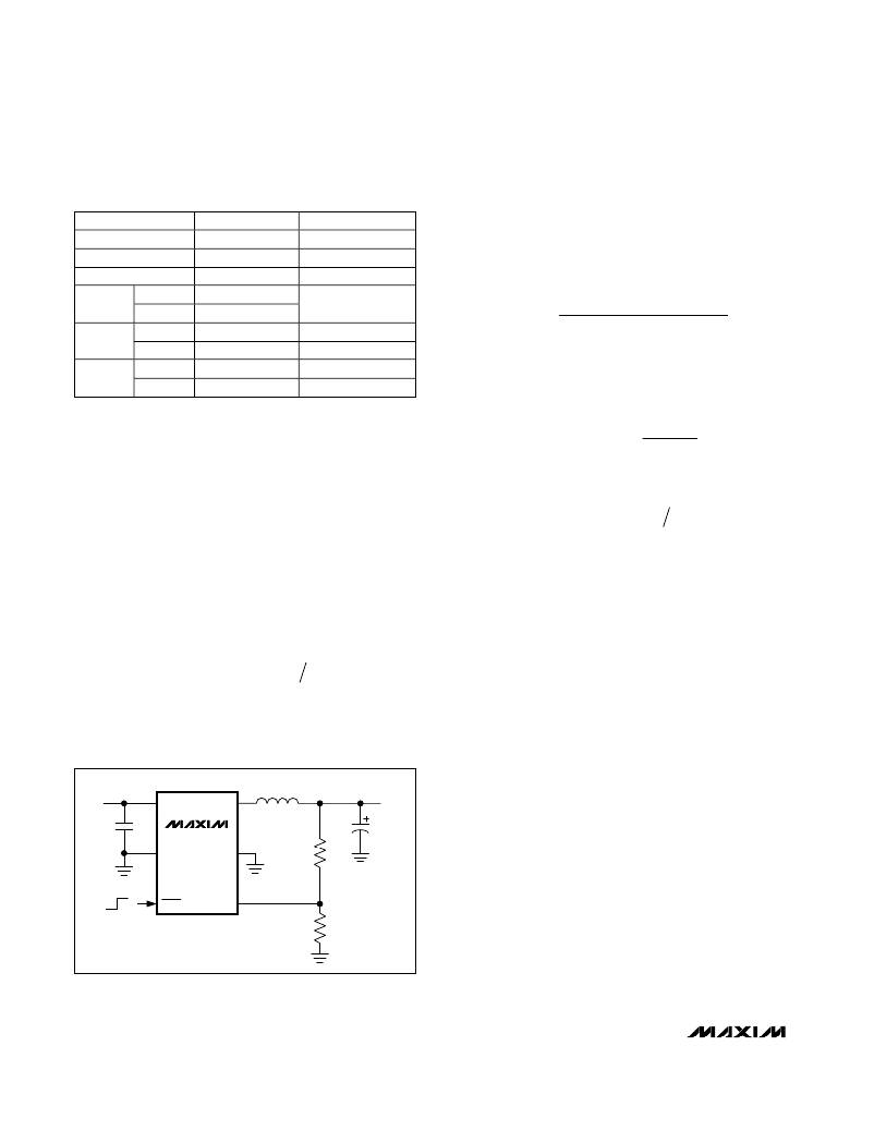
�MAX1920� Using� Tantalum� C� OUT�
�When� using� the� application� circuit� of� Figure� 4,� choose�
�R1� and� R2� such� as� to� obtain� the� desired� V� OUT� :�
�?� V� ?�
�?� V� REF� ?�
�where� R2� is� chosen� to� be� less� than� 50k� ?� and� V� REF� =�
�1.25V.� Use� 1%� or� better� resistors.�
�Layout� Considerations�
�High� switching� frequencies� make� PC� board� layout� a�
�very� important� part� of� design.� Good� design� minimizes�
�INPUT�
�2V� TO� 5.5V�
�1�
�IN�
�LX�
�6�
�L�
�OUTPUT�
�UP� TO� 400mA�
�excessive� EMI� on� the� feedback� paths� and� voltage� gra-�
�dients� in� the� ground� plane,� both� of� which� can� result� in�
�C� IN�
�2�
�MAX1920�
�AGND� PGND�
�5�
�R1�
�C� OUT�
�instability� or� regulation� errors.� Connect� the� inductor,�
�input� filter� capacitor,� and� output� filter� capacitor� as�
�close� to� the� device� as� possible,� and� keep� their� traces�
�short,� direct,� and� wide.� Connect� their� ground� pins� at� a�
�single� common� node� in� a� star� ground� configuration.�
�ON�
�OFF�
�3�
�SHDN�
�FB�
�4�
�The� external� voltage-feedback� network� should� be� very�
�close� to� the� FB� pin,� within� 0.2in� (5mm).� Keep� noisy�
�R2�
�Figure� 4.� MAX1920� Application� Circuit� Using� Tantalum� Output�
�Capacitor�
�traces,� such� as� the� LX� trace,� away� from� the� voltage-�
�feedback� network;� also� keep� them� separate,� using�
�grounded� copper.� The� MAX1920/MAX1921� evaluation�
�kit� data� sheet� includes� a� proper� PC� board� layout� and�
�routing� scheme.�
�8�
�_______________________________________________________________________________________�
�相关PDF资料 |
PDF描述 |
|---|---|
| MAX1922ESA+ | IC SW CUR LIMIT USB 8-SOIC |
| MAX1925ETC+ | IC CHARGER LI+ 12-TQFN |
| MAX1928EUB18+ | IC REG BUCK SYNC 1.8V .8A 10UMAX |
| MAX1930ESA+ | IC SW CUR LIMIT USB 8-SOIC |
| MAX1931EUB+T | IC SW CUR LIMIT USB 10-UMAX |
相关代理商/技术参数 |
参数描述 |
|---|---|
| MAX1921EVKIT | 功能描述:电源管理IC开发工具 MAX1921 Eval Kit RoHS:否 制造商:Maxim Integrated 产品:Evaluation Kits 类型:Battery Management 工具用于评估:MAX17710GB 输入电压: 输出电压:1.8 V |
| MAX1922ESA | 功能描述:电源开关 IC - USB 1A Crnt-Ltd Switch for 2 USB Ports RoHS:否 制造商:Micrel 电源电压-最小:2.7 V 电源电压-最大:5.5 V 最大工作温度:+ 85 C 最小工作温度:- 40 C 封装 / 箱体:SOIC-8 封装:Tube |
| MAX1922ESA+ | 功能描述:电源开关 IC - USB 1A Crnt-Ltd Switch for 2 USB Ports RoHS:否 制造商:Micrel 电源电压-最小:2.7 V 电源电压-最大:5.5 V 最大工作温度:+ 85 C 最小工作温度:- 40 C 封装 / 箱体:SOIC-8 封装:Tube |
| MAX1922ESA+C71073 | 功能描述:电源开关 IC - USB 1A Crnt-Ltd Switch for 2 USB Ports RoHS:否 制造商:Micrel 电源电压-最小:2.7 V 电源电压-最大:5.5 V 最大工作温度:+ 85 C 最小工作温度:- 40 C 封装 / 箱体:SOIC-8 封装:Tube |
| MAX1922ESA+T | 功能描述:电源开关 IC - USB 1A Crnt-Ltd Switch for 2 USB Ports RoHS:否 制造商:Micrel 电源电压-最小:2.7 V 电源电压-最大:5.5 V 最大工作温度:+ 85 C 最小工作温度:- 40 C 封装 / 箱体:SOIC-8 封装:Tube |
发布紧急采购,3分钟左右您将得到回复。