- 您现在的位置:买卖IC网 > PDF目录383343 > MAX1970 (Maxim Integrated Products, Inc.) Dual, 180∑ Out-of-Phase, 1.4MHz, 750mA Step- Down Regulator with POR and RSI/PFO PDF资料下载
参数资料
| 型号: | MAX1970 |
| 厂商: | Maxim Integrated Products, Inc. |
| 英文描述: | Dual, 180∑ Out-of-Phase, 1.4MHz, 750mA Step- Down Regulator with POR and RSI/PFO |
| 中文描述: | 双路、180°异相、1.4MHz、750mA、降压型调节器,带有POR和RSI/PFO |
| 文件页数: | 11/20页 |
| 文件大小: | 371K |
| 代理商: | MAX1970 |
Detailed Description
The MAX1970/MAX1971/MAX1972 are dual-output,
fixed-frequency, current-mode, PWM, step-down
DC/DC converters. The MAX1970 and MAX1972 switch
at 1.4 MHz while the MAX1971 switches at 700kHz. The
two converters on each IC switch 180
°
out of phase
with each other to reduce input ripple current. The
high-switching frequency allows use of smaller capaci-
tors for filtering and decoupling. Internal synchronous
rectifiers improve efficiency and eliminate the typical
Schottky freewheeling diode. The on-resistances of the
internal MOSFETs are used to sense the switch cur-
rents for controlling and protecting the MOSFETs, elimi-
nating current-sensing resistors to further improve
efficiency and cost.
The input voltage range is 2.6V to 5.5V. Each converter
has a three-mode feedback input. Internally, OUT1 is
set to either 3.3V or 1.8V, and OUT2 to 2.5V or 1.5V by
connecting FBSEL1 and FBSEL2 to V
CC
or GND,
respectively. When FBSEL1 or FBSEL2 are floating,
each output can be set to any voltage between 1.2V
and V
IN
through an external resistive divider. Having an
output below 1.2V is also possible (see the
Output
Voltage Selection
section).
DC-DC Controller
The MAX1970/MAX1971/MAX1972 family of step-down
converters uses a pulse-width-modulating (PWM) current-
mode control scheme. The heart of the current-mode
PWM controller is an open-loop comparator that com-
pares the integrated voltage-feedback signal against
the sum of the amplified current-sense signal and the
slope compensation ramp. At each rising edge of the
internal clock, the internal high-side MOSFET turns on
until the PWM comparator trips. During this on time,
current ramps up through the inductor, sourcing cur-
rent to the output and storing energy in a magnetic
field. The current-mode feedback system regulates the
peak inductor current as a function of the output volt-
age error signal. Since the average inductor current is
nearly the same as the peak inductor current (assum-
ing that the inductor value is relatively high to minimize
ripple current), the circuit acts as a switch-mode
transconductance amplifier. It pushes the output LC filter
pole, normally found in a voltage-mode PWM, to a higher
frequency. To preserve inner loop stability and eliminate
inductor stair casing, a slope-compensation ramp is
summed into the main PWM comparator. During the
second half of the cycle, the internal high-side MOSFET
M
Dual, 180° Out-of-Phase, 1.4MHz, 750mA Step-
Down Regulator with POR and RSI/PFO
______________________________________________________________________________________
11
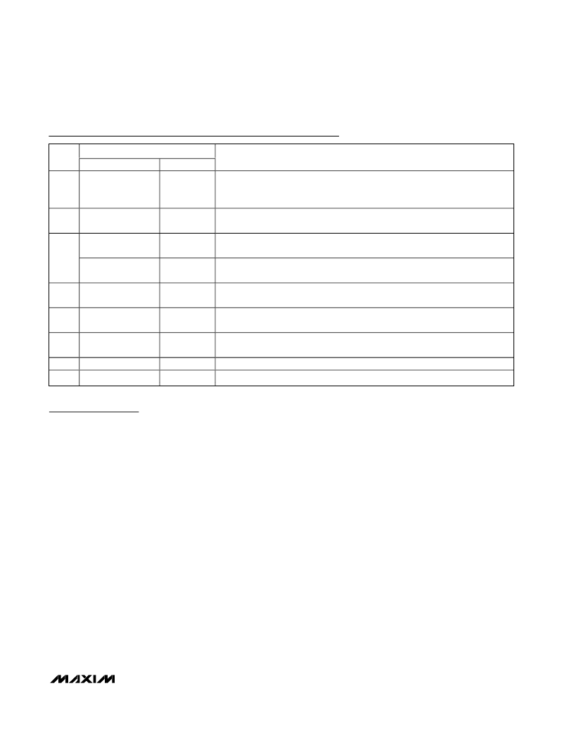
NAME
PIN
MAX1970/MAX1972
MAX1971
FUNCTION
9
POR
POR
Active-Low Power-On Reset Output. Open-drain output goes high 16.6ms
(MAX1970) or 175ms (MAX1971 or MAX1972) after both outputs reach 92% of
nominal value, and RSI (MAX1971 only) is low.
10
EN
EN
Enable Input. Drive high to turn on both OUT1 and OUT2. Drive low to place the
device in shutdown.
PFO
—
Power-Fail Output. Open-drain output goes high when V
CC
drops below 3.94V.
Useful for detecting a valid USB input voltage.
11
—
RSI
Noninverting Reset Input. Causes
POR
to go low when RSI is high. Allows
POR
to
go high 175ms after RSI falls, if outputs are in regulation.
12
FBSEL2
FBSEL2
Regulator 2 Feedback Select. Connect to V
CC
to set V
OUT2
to 2.5V. Connect to
GND to set V
OUT2
to 1.5V. Leave unconnected to use external feedback resistors.
13
FBSEL1
FBSEL1
Regulator 1 Feedback Select. Connect to V
CC
to set V
OUT1
to 3.3V. Connect to
GND to set V
OUT1
to 1.8V. Leave unconnected to use external feedback resistors.
14
IN
IN
Power-Supply Voltage. Input range from 2.6V to 5.5V. Bypass with 10μF capacitor
to PGND.
15
16
LX2
PGND
LX2
PGND
Inductor Connection 2. Connect an inductor between LX2 and OUT2.
Power Ground
Pin Description (continued)
相关PDF资料 |
PDF描述 |
|---|---|
| MAX1970EEE | Fixed-Point Digital Signal Processor 532-FCBGA |
| MAX1971 | Fixed-Point Digital Signal Processor 532-FCBGA |
| MAX1972 | Dual, 180∑ Out-of-Phase, 1.4MHz, 750mA Step- Down Regulator with POR and RSI/PFO |
| MAX1972EEE | Fixed-Point Digital Signal Processor 532-FCBGA |
| MAX1973 | Smallest 1A, 1.4MHz Step-Down Regulators |
相关代理商/技术参数 |
参数描述 |
|---|---|
| MAX19700ETM | 功能描述:ADC / DAC多通道 RoHS:否 制造商:Texas Instruments 转换速率: 分辨率:8 bit 接口类型:SPI 电压参考: 电源电压-最大:3.6 V 电源电压-最小:2 V 最大工作温度:+ 85 C 安装风格:SMD/SMT 封装 / 箱体:VQFN-40 |
| MAX19700ETM+ | 功能描述:ADC / DAC多通道 7.5Msps CODEC/AFE 1.8/2.7-3.3V RoHS:否 制造商:Texas Instruments 转换速率: 分辨率:8 bit 接口类型:SPI 电压参考: 电源电压-最大:3.6 V 电源电压-最小:2 V 最大工作温度:+ 85 C 安装风格:SMD/SMT 封装 / 箱体:VQFN-40 |
| MAX19700ETM+T | 功能描述:ADC / DAC多通道 7.5Msps CODEC/AFE 1.8/2.7-3.3V RoHS:否 制造商:Texas Instruments 转换速率: 分辨率:8 bit 接口类型:SPI 电压参考: 电源电压-最大:3.6 V 电源电压-最小:2 V 最大工作温度:+ 85 C 安装风格:SMD/SMT 封装 / 箱体:VQFN-40 |
| MAX19700ETM-T | 功能描述:ADC / DAC多通道 RoHS:否 制造商:Texas Instruments 转换速率: 分辨率:8 bit 接口类型:SPI 电压参考: 电源电压-最大:3.6 V 电源电压-最小:2 V 最大工作温度:+ 85 C 安装风格:SMD/SMT 封装 / 箱体:VQFN-40 |
| MAX19700EVCMOD2 | 功能描述:ADC / DAC多通道 Evaluation Kit/Evaluation System for the MAX19700 RoHS:否 制造商:Texas Instruments 转换速率: 分辨率:8 bit 接口类型:SPI 电压参考: 电源电压-最大:3.6 V 电源电压-最小:2 V 最大工作温度:+ 85 C 安装风格:SMD/SMT 封装 / 箱体:VQFN-40 |
发布紧急采购,3分钟左右您将得到回复。