- 您现在的位置:买卖IC网 > PDF目录18825 > MAX2121ETI+ (Maxim Integrated)RF RECEIVER PDF资料下载
参数资料
| 型号: | MAX2121ETI+ |
| 厂商: | Maxim Integrated |
| 文件页数: | 17/19页 |
| 文件大小: | 0K |
| 描述: | RF RECEIVER |
| 标准包装: | 60 |
| 功能: | 调谐器 |
| 频率: | 925MHz ~ 2.175GHz |
| RF 型: | L 频带 |
| 次要属性: | 直接转换 |
| 封装/外壳: | 28-WFQFN 裸露焊盘 |
| 包装: | 管件 |
�� �
�
�Complete� Direct-Conversion� L-Band� Tuner�
�Integer� portion:�
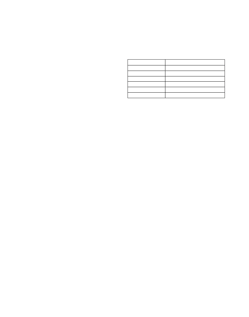
�Table� 17.� ADC� Trip� Points� and� Lock� Status�
�N� =� 80�
�N� [� 14:8� ]� =� 0�
�N� [� 7:0� ]� =� 0101� 0000�
�Fractional� portion:�
�F� =� 0.370370� x� 2� 20� =� 388,361� (round� up� the� decimal� portion)�
�F� =� 0101� 1110� 1101� 0000� 1001�
�Note:� When� changing� LO� frequencies,� all� the� divider�
�registers� (integer� and� fractional)� must� be� programmed�
�ADC[2:0]�
�000�
�001�
�010�
�101�
�110�
�111�
�LOCK� STATUS�
�Out� of� lock�
�Locked�
�VAS� locked�
�VAS� locked�
�Locked�
�Out� of� lock�
�to� activate� the� VAS� function� regardless� of� whether� indi-�
�vidual� registers� are� changed.�
�VCO� Autoselect� (VAS)�
�The� MAX2121� includes� 24� VCOs.� The� local� oscillator�
�frequency� can� be� manually� selected� by� programming�
�the� VCO[4:0]� bits� in� the� VCO� register.� The� selected� VCO�
�is� reported� in� the� Status� Byte-2� register� (see� Table� 15).�
�Alternatively,� the� MAX2121� can� be� set� to� autonomously�
�choose� a� VCO� by� setting� the� VAS� bit� in� the� VCO� regis-�
�ter� to� logic-high.� The� VAS� routine� is� initiated� once� the�
�F-Divider� LSB� register� word� (register� 5)� is� loaded.�
�Thus� it� is� important� to� write� register� 5� after� any� of� the�
�following� PLL� related� bits� have� been� changed:�
�N-Divider� bits� (registers� 1� and/or� 2)�
�F-Divider� bits� (registers� 3� and/or� 4)�
�Reference� Divider� bits� (register� 6)�
�D24,� CPS,� or� ICP� bits� (register� 7)�
�This� will� ensure� all� intended� bits� have� been� pro-�
�grammed� before� the� VAS� is� initiated� and� the� PLL� is�
�locked.� The� VCO� value� programmed� in� the� VCO[4:0]�
�register� serves� as� the� starting� point� for� the� automatic�
�VCO� selection� process.�
�During� the� selection� process,� the� VASE� bit� in� the� Status�
�Byte-1� register� is� cleared� to� indicate� the� autoselection�
�function� is� active.� Upon� successful� completion,� bits� VASE�
�and� VASA� are� set� and� the� VCO� selected� is� reported� in� the�
�Status� Byte-2� register� (see� Table� 15).� If� the� search� is�
�unsuccessful,� VASA� is� cleared� and� VASE� is� set.� This� indi-�
�cates� that� searching� has� ended� but� no� good� VCO� has�
�been� found,� and� occurs� when� trying� to� tune� to� a� frequen-�
�cy� outside� the� VCO’s� specified� frequency� range.�
�Refer� to� Application� Note� 4256:� Extended� Characterization�
�for� the� MAX2112/MAX2120� Satellite� Tuners.�
�Table� 17� summarizes� the� ADC� output� bits� and� the� VCO�
�lock� indication.� The� VCO� autoselect� routine� only� selects�
�a� VCO� in� the� “VAS� locked”� range.� This� allows� room� for�
�a� VCO� to� drift� over� temperature� and� remain� in� a� valid�
�“locked”� range.�
�The� ADC� must� first� be� enabled� by� setting� the� ADE� bit� in�
�the� VCO� register.� The� ADC� reading� is� latched� by� a� sub-�
�sequent� programming� of� the� ADC� latch� bit� (ADL� =� 1).�
�The� ADC� value� is� reported� in� the� Status� Byte-2� register�
�(see� Table� 15).�
�Standby� Mode�
�The� MAX2121� features� normal� operating� mode� and�
�standby� mode� using� the� I� 2� C� interface.� Setting� a� logic-�
�high� to� the� STBY� bit� in� the� Control� register� puts� the�
�device� into� standby� mode,� during� which� only� the� 2-�
�wire-compatible� bus,� the� crystal� oscillator,� the� XTAL�
�buffer,� and� the� XTAL� buffer� divider� are� active.�
�In� all� cases,� register� settings� loaded� prior� to� entering�
�shutdown� are� saved� upon� transition� back� to� active�
�mode.� Default� register� values� are� provided� for� the�
�user’s� convenience� only.� It� is� the� user’s� responsibility� to�
�load� all� the� registers� no� sooner� than� 100μs� after� the�
�device� is� powered� up.�
�Layout� Considerations�
�The� MAX2121� EV� kit� serves� as� a� guide� for� PCB� layout.�
�Keep� RF� signal� lines� as� short� as� possible� to� minimize�
�losses� and� radiation.� Use� controlled� impedance� on� all�
�high-frequency� traces.� For� proper� operation,� the�
�exposed� paddle� must� be� soldered� evenly� to� the� board’s�
�ground� plane.� Use� abundant� vias� beneath� the� exposed�
�paddle� for� maximum� heat� dissipation.� Use� abundant�
�ground� vias� between� RF� traces� to� minimize� undesired�
�coupling.� Bypass� each� V� CC� pin� to� ground� with� a� 1nF�
�capacitor� placed� as� close� as� possible� to� the� pin.�
�3-Bit� ADC�
�The� MAX2121� has� an� internal� 3-bit� ADC� connected� to�
�the� VCO� tune� pin� (TUNEVCO).� This� ADC� can� be� used�
�for� checking� the� lock� status� of� the� VCOs.�
�17�
�相关PDF资料 |
PDF描述 |
|---|---|
| CD421090B | SCR MOD ISO DUAL 1000V 90A |
| MAX2750EUA+ | IC OSC VOLT CNTRL 8-UMAX |
| CD420890B | SCR MOD ISO DUAL 800V 90A |
| 6356-48 | KIT ALLIG CLIP PATCH CORD 48" |
| T620062004DN | SCR PHASE CTRL MOD 600V 200A |
相关代理商/技术参数 |
参数描述 |
|---|---|
| MAX2121ETI+ | 功能描述:调谐器 Direct-Conversion L-Band Tuner RoHS:否 制造商:NXP Semiconductors 功能: 噪声系数: 工作电源电压: 最小工作温度: 最大工作温度: |
| MAX2121ETI+T | 功能描述:调谐器 Direct-Conversion L-Band Tuner RoHS:否 制造商:NXP Semiconductors 功能: 噪声系数: 工作电源电压: 最小工作温度: 最大工作温度: |
| MAX2121EVKIT# | 功能描述:射频开发工具 MAX2121 Eval Kit RoHS:否 制造商:Taiyo Yuden 产品:Wireless Modules 类型:Wireless Audio 工具用于评估:WYSAAVDX7 频率: 工作电源电压:3.4 V to 5.5 V |
| MAX212C/D | 功能描述:RS-232接口集成电路 +3V Powered Low-Power True RS-232 Transceiver RoHS:否 制造商:Exar 数据速率:52 Mbps 工作电源电压:5 V 电源电流:300 mA 工作温度范围:- 40 C to + 85 C 安装风格:SMD/SMT 封装 / 箱体:LQFP-100 封装: |
| MAX212CAG | 功能描述:RS-232接口集成电路 RoHS:否 制造商:Exar 数据速率:52 Mbps 工作电源电压:5 V 电源电流:300 mA 工作温度范围:- 40 C to + 85 C 安装风格:SMD/SMT 封装 / 箱体:LQFP-100 封装: |
发布紧急采购,3分钟左右您将得到回复。