- 您现在的位置:买卖IC网 > PDF目录11010 > MAX260BEWG+ (Maxim Integrated Products)IC FILTER ACT MPU PROG 24-SOIC PDF资料下载
参数资料
| 型号: | MAX260BEWG+ |
| 厂商: | Maxim Integrated Products |
| 文件页数: | 14/26页 |
| 文件大小: | 0K |
| 描述: | IC FILTER ACT MPU PROG 24-SOIC |
| 产品培训模块: | Lead (SnPb) Finish for COTS Obsolescence Mitigation Program |
| 标准包装: | 30 |
| 滤波器类型: | 通用开关电容器 |
| 频率 - 截止或中心: | 7.5kHz |
| 滤波器数: | 2 |
| 滤波器阶数: | 2nd |
| 电源电压: | 4.74 V ~ 12.6 V,±2.37 V ~ 6.3 V |
| 安装类型: | 表面贴装 |
| 封装/外壳: | 24-SOIC(0.295",7.50mm 宽) |
| 供应商设备封装: | 24-SOIC W |
| 包装: | 管件 |
MAX260/MAX261/MAX262
Microprocessor Programmable
Universal Active Filters
______________________________________________________________________________________
21
mode 1 the maximum signal is 0 times the input signal,
the input should not exceed ±(2/Q)V, or ±1V in this case.
Clock Feedthrough and Noise
Typical wideband noise for MAX260 series devices is
0.5mVP-P from DC to 100kHz. The noise is virtually
independent of clock frequency. In multistage filters,
the section with the highest Q should be placed first for
lower output noise.
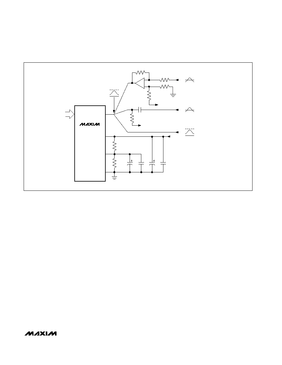
The output waveform of the MAX260 series and other
switched capacitor filters appears as a sampled signal
with stepping or “staircasing” of the output waveform
occurring at the internal sample rate (fCLK/2). This step-
ping, if objectionable, can be removed by adding a sin-
gle-pole AC filter. With no input signal, clock-related
feedthrough is approximately 8mVP-P. This can also be
attenuated with an RC-smoothing filter as shown with
the MAX261 in Figure 17.
Some noise also can be generated at the filter outputs
by transitions at the logic inputs. If this is objectionable,
the digital lines should be buffered from the device by
logic gates as shown in Figure 6.
Input Impedance
The input to each filter is the switched capacitor circuit
shown in Figure 18. In the MAX260, the input capacitor
charges to the input voltage VIN during the first half
clock cycle. During the second half-cycle, its charge is
transferred to the feedback capacitor. The resultant
input impedance can be approximated by:
RIN = 1 / (CINfCLK / 2) = 2 / (CINfCLK).
CIN is around 12pF, hence, for a clock frequency of
500kHz, RIN = 333k
. The input also has about 5pF of
fixed capacitance to ground.
The MAX261/MAX262 input structure is shown in Figure
19. Here CA = 12pF and CB = 0.016pF and only CB is
switched, so the input resistance is 750 times larger
compared to the MAX260 (RIN = 250M
). The
MAX261/MAX262 have a fixed capacitance of approxi-
mately 5pF to ground.
f0 and Q at Low Sample Rates
When low fCLK/f0 ratios and low Q settings are select-
ed, deviation from ideal continuous filter response can
be noticeable in some designs. This is due to interac-
tion between Q and f0 at low fCLK/f0 ratios and Qs. The
data in Figure 20 quantifies these differences. Since the
MAX260
MAX261
MAX262
WR
A0–A3
D0, D1
INA
OR
INB
CMOS
LOGIC
LEVELS
V+
V-
GND
0.1
F
0.1
F
+5V
4.7
F
4.7k
4.7k
NOTE: OP-AMP LEVEL SHIFT CIRCUIT HAS A GAIN OF 0.5 FROM V*.
VIN
TO V+
TO GND PIN
2.5k
7.5k
10k
10k
+
-
SEE
NOTE
VIN
4.7
F
5V
0V
5V
0V
ANY DC
0V
Figure 16. Power Supply and Input Connections for Single Supply Operation
相关PDF资料 |
PDF描述 |
|---|---|
| MAX274BENG+ | IC FILTER ACTIVE 24-DIP |
| MAX268BEWG+ | IC FILTER BANDPASS PROG 24-SOIC |
| MAX261BEWG+ | IC FILTER ACT MPU PROG 24-SOIC |
| MC9S08RG60FGE | IC MCU 60K FLASH 8MHZ 44-LQFP |
| MAX267BEWG+ | IC FILTER BANDPASS PROG 24-SOIC |
相关代理商/技术参数 |
参数描述 |
|---|---|
| MAX260BEWG+ | 功能描述:有源滤波器 MPU Programmable Univ Active Filter RoHS:否 制造商:Maxim Integrated 通道数量:1 截止频率:150 KHz 电源电压-最大:11 V 电源电压-最小:4.74 V 最大工作温度:+ 85 C 安装风格:Through Hole 封装 / 箱体:PDIP N 封装:Tube |
| MAX260BEWG+T | 功能描述:有源滤波器 MPU Programmable Univ Active Filter RoHS:否 制造商:Maxim Integrated 通道数量:1 截止频率:150 KHz 电源电压-最大:11 V 电源电压-最小:4.74 V 最大工作温度:+ 85 C 安装风格:Through Hole 封装 / 箱体:PDIP N 封装:Tube |
| MAX260BEWG-T | 功能描述:有源滤波器 RoHS:否 制造商:Maxim Integrated 通道数量:1 截止频率:150 KHz 电源电压-最大:11 V 电源电压-最小:4.74 V 最大工作温度:+ 85 C 安装风格:Through Hole 封装 / 箱体:PDIP N 封装:Tube |
| MAX260BMRG | 功能描述:有源滤波器 RoHS:否 制造商:Maxim Integrated 通道数量:1 截止频率:150 KHz 电源电压-最大:11 V 电源电压-最小:4.74 V 最大工作温度:+ 85 C 安装风格:Through Hole 封装 / 箱体:PDIP N 封装:Tube |
| MAX260SOFT | 功能描述:有源滤波器 RoHS:否 制造商:Maxim Integrated 通道数量:1 截止频率:150 KHz 电源电压-最大:11 V 电源电压-最小:4.74 V 最大工作温度:+ 85 C 安装风格:Through Hole 封装 / 箱体:PDIP N 封装:Tube |
发布紧急采购,3分钟左右您将得到回复。