- 您现在的位置:买卖IC网 > Datasheet目录42 > MAX31826MUA+T (Maxim Integrated)IC TEMP SENSOR DIGITAL 8UMAX Datasheet资料下载
参数资料
| 型号: | MAX31826MUA+T |
| 厂商: | Maxim Integrated |
| 文件页数: | 10/22页 |
| 文件大小: | 1648K |
| 描述: | IC TEMP SENSOR DIGITAL 8UMAX |
| 标准包装: | 2,500 |
| 系列: | 1-Wire® |
| 功能: | 温度监控系统(传感器) |
| 传感器类型: | 内部 |
| 感应温度: | -55°C ~ 125°C |
| 精确度: | ±2°C |
| 拓扑: | 寄存器库,变签式暂存器 |
| 输出类型: | 1-Wire? |
| 输出警报: | 无 |
| 输出风扇: | 无 |
| 电源电压: | 3 V ~ 3.7 V |
| 工作温度: | -55°C ~ 125°C |
| 安装类型: | 表面贴装 |
| 封装/外壳: | 8-TSSOP,8-MSOP(0.118",3.00mm 宽) |
| 供应商设备封装: | 8-uMAX |
| 包装: | 带卷 (TR) |
Maxim Integrated Products 10
MAX31826
1-Wire Digital Temperature Sensor
with 1Kb Lockable EEPROM
CRC Generation
CRC bytes are provided as part of the devices 64-bit
ROM code, in the 9th byte of Scratchpad 1, and for
Scratchpad 2 values. The ROM code CRC is calculated
from the first 56 bits of the ROM code and is contained in
the most significant byte of the ROM. The two scratchpad
CRCs are calculated from the data in each scratchpad,
and therefore changes when the data in it associated
scratchpad changes. The CRCs provide the bus mas-
ter with a method of data validation when data is read
from the device. To verify that data has been read cor-
rectly, the bus master must recalculate the CRC from
the received data and then compare this value to either
the ROM code CRC (for ROM reads) or to the scratch-
pads CRC (for scratchpad reads). If the calculated CRC
matches the read CRC, the data has been received
error-free. The comparison of CRC values and the deci-
sion to continue with an operation are determined entirely
by the bus master. There is no circuitry inside the device
that prevents a command sequence from proceeding if
the device CRC (ROM or scratchpad) does not match the
value generated by the bus master.
The equivalent polynomial function of the CRC (ROM or
scratchpad) is:
CRC = X
8
+ X
5
+ X
4
+ 1
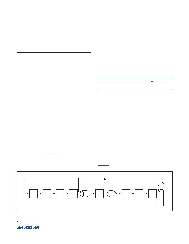
The bus master can recalculate the CRC and compare it
to the CRC values from the device using the polynomial
generator shown in Figure 5. This circuit consists of a
shift register and XOR gates, and the shift register bits
are initialized to 0. Starting with the least significant bit
of the ROM code or the least significant bit of byte 0 in
the scratchpad, one bit at a time should shifted into the
shift register. After shifting in the 56th bit from the ROM
or the most significant bit of byte 7 from the Scratchpad 1
or byte 10 from Scratchpad 2, the polynomial generator
contains the recalculated CRC. Next, the 8-bit ROM code
or scratchpad CRC from the device must be shifted into
the circuit. At this point, if the recalculated CRC was
correct, the shift register contains all zeros. Additional
information about the Maxim 1-Wire CRC is available in
Application Note 27: Understanding and Using Cyclic
Redundancy Checks with Maxim iButton
?/DIV>
Products.
1-Wire Bus System
The 1-Wire bus system uses a single bus master to con-
trol one or more slave devices. The MAX31826 is always
a slave. When there is only one slave on the bus, the
system is referred to as a single-drop system; the system
is multidrop if there are multiple slaves on the bus. All
data and commands are transmitted least significant bit
first over the 1-Wire bus.
The following discussion of the 1-Wire bus system is
broken down into three topics: hardware configuration,
transaction sequence, and 1-Wire signaling (signal types
and timing).
Hardware Configuration
The 1-Wire bus has by definition only a single data line.
Each device (master or slave) interfaces to the data line
by using an open-drain or three-state port. This allows
each device to
release
the data line when the device
is not transmitting data so the bus is available for use by
another device. The devices 1-Wire port (DQ) is open
drain with an internal circuit equivalent to that shown in
Figure 6.
Figure 5. CRC Generator
iButton is a registered trademark of Maxim Integrated Products, Inc.
1ST
STAGE
2ND
STAGE
3RD
STAGE
4TH
STAGE
7TH
STAGE
8TH
STAGE
6TH
STAGE
5TH
STAGE
X
0
X
1
X
2
X
3
X
4
POLYNOMIAL = X
8
+ X
5
+ X
4
+ 1
INPUT DATA
X
5
X
6
X
7
X
8
相关PDF资料 |
PDF描述 |
|---|---|
| MAX4006EUT+T | IC CURRENT MONITOR 1% SOT23-6 |
| MAX4008EUT+T | IC CURRENT MONITOR 1% SOT23-6 |
| MAX4370ESA+T | IC CNTRLR HOT-SWAP 8-SOIC |
| MAX4995AFAVB+ | IC CURRENT SWITCH 10% 10UTQFN |
| MAX5900AAEUT+T | IC HOT-SWAP CONTROLLER SOT23-6 |
相关代理商/技术参数 |
参数描述 |
|---|---|
| MAX3182EEUK | 制造商:Maxim Integrated Products 功能描述:+-15KV ESD-PROTECTED 0.5MA +3V TO - Rail/Tube |
| MAX3182EEUK+ | 制造商:Maxim Integrated Products 功能描述:LINE RCVR 1RX 5PIN SOT-23 - Rail/Tube 制造商:Maxim Integrated Products 功能描述:Single Receiver RS-232 5-Pin SOT-23 Bulk |
| MAX3182EEUK+T | 功能描述:RS-232接口集成电路 .5uA 3-5.5V 1.5Mbps RS-232 Rcvr RoHS:否 制造商:Exar 数据速率:52 Mbps 工作电源电压:5 V 电源电流:300 mA 工作温度范围:- 40 C to + 85 C 安装风格:SMD/SMT 封装 / 箱体:LQFP-100 封装: |
| MAX3182EEUK-T | 功能描述:RS-232接口集成电路 RoHS:否 制造商:Exar 数据速率:52 Mbps 工作电源电压:5 V 电源电流:300 mA 工作温度范围:- 40 C to + 85 C 安装风格:SMD/SMT 封装 / 箱体:LQFP-100 封装: |
| MAX3182EUK | 制造商:Maxim Integrated Products 功能描述:3V TO 5.5V 15MBPS RS-232 RECEIVER - Rail/Tube |
发布紧急采购,3分钟左右您将得到回复。