- 您现在的位置:买卖IC网 > Datasheet目录42 > MAX31826MUA+T (Maxim Integrated)IC TEMP SENSOR DIGITAL 8UMAX Datasheet资料下载
参数资料
| 型号: | MAX31826MUA+T |
| 厂商: | Maxim Integrated |
| 文件页数: | 3/22页 |
| 文件大小: | 1648K |
| 描述: | IC TEMP SENSOR DIGITAL 8UMAX |
| 标准包装: | 2,500 |
| 系列: | 1-Wire® |
| 功能: | 温度监控系统(传感器) |
| 传感器类型: | 内部 |
| 感应温度: | -55°C ~ 125°C |
| 精确度: | ±2°C |
| 拓扑: | 寄存器库,变签式暂存器 |
| 输出类型: | 1-Wire? |
| 输出警报: | 无 |
| 输出风扇: | 无 |
| 电源电压: | 3 V ~ 3.7 V |
| 工作温度: | -55°C ~ 125°C |
| 安装类型: | 表面贴装 |
| 封装/外壳: | 8-TSSOP,8-MSOP(0.118",3.00mm 宽) |
| 供应商设备封装: | 8-uMAX |
| 包装: | 带卷 (TR) |
? Maxim Integrated Products 3
MAX31826
1-Wire Digital Temperature Sensor
with 1Kb Lockable EEPROM
Note 1: Limits are 100% production tested at T
A
= +25癈 and/or T
A
= +85癈. Limits over the operating temperature range and
relevant supply voltage range are guaranteed by design and characterization. Typical values are not guaranteed.
Note 2: All voltages are referenced to ground.
Note 3: The pullup supply voltage specification assumes that the pullup device is ideal, and therefore the high level of the pullup
is equal to V
PU
. To meet the devices V
IH
specification, the actual supply rail for the strong pullup transistor must include
margin for the voltage drop across the transistor when it is turned on; thus: V
PU_ACTUAL
= V
PU_IDEAL
+ V
TRANSISTOR
.
Note 4: Guaranteed by design. These limits represent a three sigma distribution.
Note 5: To guarantee a presence pulse under low-voltage parasite-power conditions, V
ILMAX
might need to be reduced to as low
as 0.5V.
Note 6: Logic-high voltages are specified at a 1mA source current.
Note 7: Standby current specified up to T
A
= +70NC. Standby current typically is 3FA at T
A
= +125NC.
Note 8: To minimize I
DDS
, DQ should be within the following ranges: V
GND
P V
DQ
P V
GND
+ 0.3V or V
DD
- 0.3V P V
DQ
P V
DD
.
Note 9: Active current refers to supply current during active temperature conversions or EEPROM writes.
Note 10: DQ line is high (high-impedance state).
Note 11: See the 1-Wire Timing Diagrams.
Note 12: Under parasite power, if t
RSTL
> 960Fs, a power-on reset (POR) can occur.
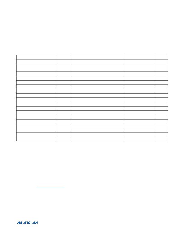
AC ELECTRICAL CHARACTERISTICS
(V
DD
= 3.0V to 3.7V, T
A
= -55癈 to +125癈, unless otherwise noted.) (Note 1)
PARAMETER
SYMBOL
CONDITIONS
MIN
TYP
MAX
UNITS
Temperature Conversion Time
t
CONV
12-bit resolution
150
ms
Time to Strong Pullup On
t
SPON
Start Convert T command, or Copy
Scratchpad 2 command issued
10
Fs
Time Slot
t
SLOT
(Note 11)
60
120
Fs
Recovery Time
t
REC
(Note 11)
1
Fs
Write-Zero Low Time
t
LOW0
(Note 11)
60
120
Fs
Write-One Low Time
t
LOW1
(Note 11)
1
15
Fs
Read Data Valid
t
RDV
(Note 11)
15
Fs
Reset Time High
t
RSTH
(Note 11)
480
Fs
Reset Time Low
t
RSTL
(Notes 11, 12)
480
Fs
Presence-Detect High
t
PDHIGH
(Note 11)
15
60
Fs
Presence-Detect Low
t
PDLOW
(Note 11)
60
240
Fs
DQ Capacitance
C
IN/OUT
25
pF
AD0AD3 Capacitance
C
IN_AD
50
pF
NONVOLATILE MEMORY
EEPROM Write/Erase Cycles
N
EEWR
At T
A
= +25癈
200k
At T
A
= +85癈 (worst case)
50k
EEPROM Data Retention
t
EEDR
At T
A
= +85癈 (worst case)
40
Years
EEPROM Write Time
t
WR
20
25
ms
相关PDF资料 |
PDF描述 |
|---|---|
| MAX4006EUT+T | IC CURRENT MONITOR 1% SOT23-6 |
| MAX4008EUT+T | IC CURRENT MONITOR 1% SOT23-6 |
| MAX4370ESA+T | IC CNTRLR HOT-SWAP 8-SOIC |
| MAX4995AFAVB+ | IC CURRENT SWITCH 10% 10UTQFN |
| MAX5900AAEUT+T | IC HOT-SWAP CONTROLLER SOT23-6 |
相关代理商/技术参数 |
参数描述 |
|---|---|
| MAX3182EEUK | 制造商:Maxim Integrated Products 功能描述:+-15KV ESD-PROTECTED 0.5MA +3V TO - Rail/Tube |
| MAX3182EEUK+ | 制造商:Maxim Integrated Products 功能描述:LINE RCVR 1RX 5PIN SOT-23 - Rail/Tube 制造商:Maxim Integrated Products 功能描述:Single Receiver RS-232 5-Pin SOT-23 Bulk |
| MAX3182EEUK+T | 功能描述:RS-232接口集成电路 .5uA 3-5.5V 1.5Mbps RS-232 Rcvr RoHS:否 制造商:Exar 数据速率:52 Mbps 工作电源电压:5 V 电源电流:300 mA 工作温度范围:- 40 C to + 85 C 安装风格:SMD/SMT 封装 / 箱体:LQFP-100 封装: |
| MAX3182EEUK-T | 功能描述:RS-232接口集成电路 RoHS:否 制造商:Exar 数据速率:52 Mbps 工作电源电压:5 V 电源电流:300 mA 工作温度范围:- 40 C to + 85 C 安装风格:SMD/SMT 封装 / 箱体:LQFP-100 封装: |
| MAX3182EUK | 制造商:Maxim Integrated Products 功能描述:3V TO 5.5V 15MBPS RS-232 RECEIVER - Rail/Tube |
发布紧急采购,3分钟左右您将得到回复。