- 您现在的位置:买卖IC网 > PDF目录16559 > MAX5059AUI+T (Maxim Integrated Products)IC DRVR SYNC RECT 28-TSSOP PDF资料下载
参数资料
| 型号: | MAX5059AUI+T |
| 厂商: | Maxim Integrated Products |
| 文件页数: | 15/25页 |
| 文件大小: | 0K |
| 描述: | IC DRVR SYNC RECT 28-TSSOP |
| 产品培训模块: | Lead (SnPb) Finish for COTS Obsolescence Mitigation Program |
| 标准包装: | 2,500 |
| 应用: | 电源 |
| 电流 - 电源: | 2.5mA |
| 电源电压: | 9.3 V ~ 28 V |
| 工作温度: | -40°C ~ 125°C |
| 安装类型: | 表面贴装 |
| 封装/外壳: | 28-SOIC(0.173",4.40mm 宽)裸露焊盘 |
| 供应商设备封装: | 28-TSSOP 裸露焊盘 |
| 包装: | 带卷 (TR) |
�� �
�
�Parallelable� Secondary-Side� Synchronous� Rectifier�
�Driver� and� Feedback-Generator� Controller� ICs�
�Reverse-Current� Prevention�
�in� Synchronous� Rectifiers�
�One� benefit� of� secondary-side� synchronous� rectifica-�
�tion� is� increased� efficiency.� Another� benefit� is� that� it�
�allows� the� inductor� current� to� remain� continuous�
�throughout� the� operating� load� range.� This� results� in�
�constant� loop� dynamics� that� are� easy� to� compensate.�
�In� some� cases,� it� may� be� necessary� to� turn� off� the� free-�
�wheeling� MOSFET� when� the� current� through� this� device�
�attempts� to� flow� from� drain� to� source.� Turning� off� this�
�MOSFET� can� be� done� to� enhance� efficiency� at� low� out-�
�put� current.� When� multiple� power� supplies� are� paral-�
�leled,� the� power� supply� with� the� highest� output� voltage�
�has� a� tendency� to� source� current� into� the� power-supply�
�outputs� with� lower� output� voltage.� Turning� off� the� free-�
�wheeling� MOSFET� also� prevents� this� current� back-flow.�
�When� the� inductor� current� is� allowed� to� become� dis-�
�continuous,� the� loop� dynamics� change� and� the� circuit�
�must� be� compensated� accordingly� to� accommodate�
�stable� continuous� and� discontinuous� mode� operation.�
�Turning� off� the� freewheeling� MOSFET� is� accomplished�
�by� using� the� zero-current� comparator� (pins� ZCP� and�
�ZCN).� Use� this� comparator� to� sense� reverse� current� in�
�the� freewheeling� MOSFET� and� turn� off� the� device� by�
�pulling� QSYNC� low.� An� internal� latch� prevents� the� free-�
�wheeling� MOSFET� from� turning� on� until� the� off-time� of�
�the� next� cycle.�
�Reference� Current�
�The� MAX5058/MAX5059� do� not� have� an� explicit� refer-�
�ence� voltage� generator.� Instead,� they� contain� a� 1%-�
�accurate� trimmed� 50μA� current� source.� This� allows� sig-�
�nificant� flexibility� in� setting� the� reference� voltage.� In�
�some� cases,� the� output-voltage� resistive� divider,� con-�
�connected� from� I� REF� to� GND.� INV� is� the� inverting� input�
�and� connects� to� the� center� of� a� resistive� divider� from�
�OUT� to� INV� to� GND.� The� output� of� the� error� amplifier,�
�COMPV,� connects� to� the� cathode� of� the� LED� in� the�
�optocoupler� to� control� the� diode� current� that� transmits�
�the� error� signal� back� to� the� primary-side� controller.� An�
�open-drain-output� error� amplifier� simplifies� interfacing�
�with� the� feedback� optocoupler.� Use� this� error� amplifier�
�the� same� way� as� the� industry-standard� TL431� shunt� ref-�
�erence.� The� open-drain� output� provides� flexibility� that�
�may� be� necessary� when� additional� functionality� such�
�as� secondary� current-limit� regulation� is� required.� Unlike�
�the� TL431,� the� output� of� the� internal� error� amplifier� of�
�the� MAX5058/MAX5059� is� guaranteed� to� be� a� maxi-�
�mum� of� 200mV� with� a� 5mA� drain� current,� compared� to�
�2.5V� for� the� TL431� and� 1.24V� for� the� TLV431.�
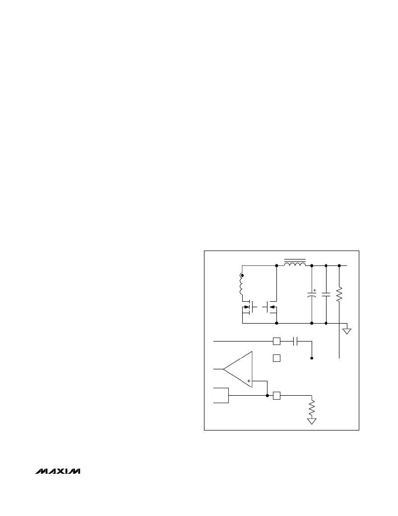
�In� some� cases,� it� is� possible� to� avoid� the� use� of� the� out-�
�put� voltage-divider� (R1� and� R2)� by� connecting� INV� to�
�the� output� through� just� R1.� This� eliminates� the� voltage�
�tolerance� errors� caused� by� R1� and� R2.� Output� voltage�
�in� this� configuration� is� set� directly� by� using� a� suitable�
�resistor� at� I� REF� .� Figure� 7� shows� this� configuration.�
�V� OUT�
�R1�
�sisting� of� R1� and� R2� in� the� Typical� Application� Circuit� ,�
�can� be� eliminated� by� selecting� a� suitable� resistor� value�
�at� the� I� REF� pin.� This� reduces� the� error� that� the� output�
�voltage-divider� may� add.� Use� a� low-value� bypass�
�capacitance� at� this� pin� to� eliminate� noise.� Typical� values�
�COMPV�
�13�
�INV�
�14�
�C28�
�for� this� capacitance� are� calculated� by� considering� the�
�pole� that� it� presents� with� R12.� This� pole� must� be� placed�
�well� beyond� the� frequency� range� of� interest� of� the� cur-�
�rent-share� loop.� Use� values� less� than� 2.2nF.�
�Error� Amplifier�
�The� MAX5058/MAX5059� incorporate� a� 1.3MHz� unity�
�gain-bandwidth� error� amplifier� with� inputs� INV,� I� REF� ,�
�and� output� COMPV.� I� REF� is� the� noninverting� input� and�
�also� serves� as� the� reference� voltage� generator� with� the�
�I� REF�
�50� μ� A�
�E/A�
�I� REF�
�12�
�V� OUT� =� (50� μ� A)� x� R12�
�FOR:� 0.5V� ≤� V� OUT� ≤� 2.5V�
�R12�
�internal� 50μA� current� source� and� the� external� resistor�
�Figure� 7.� Output� Voltage� Regulation� for� 0.5V� ≤� VOUT� ≤� 2.5V�
�______________________________________________________________________________________�
�15�
�相关PDF资料 |
PDF描述 |
|---|---|
| ECM24DTKN | CONN EDGECARD 48POS DIP .156 SLD |
| TCM810LENB713 | IC RESET MONITOR 4.63V SOT23B |
| ECM24DTKH | CONN EDGECARD 48POS DIP .156 SLD |
| H0PPH-2036M | DIP CABLE - HDP20H/AE20M/HDP20H |
| ECM24DTKD | CONN EDGECARD 48POS DIP .156 SLD |
相关代理商/技术参数 |
参数描述 |
|---|---|
| MAX5059EUI | 功能描述:功率驱动器IC Secondary Side Synch Rectifier Driver RoHS:否 制造商:Micrel 产品:MOSFET Gate Drivers 类型:Low Cost High or Low Side MOSFET Driver 上升时间: 下降时间: 电源电压-最大:30 V 电源电压-最小:2.75 V 电源电流: 最大功率耗散: 最大工作温度:+ 85 C 安装风格:SMD/SMT 封装 / 箱体:SOIC-8 封装:Tube |
| MAX5059EUI+ | 功能描述:功率驱动器IC Secondary Side Synch Rectifier Driver RoHS:否 制造商:Micrel 产品:MOSFET Gate Drivers 类型:Low Cost High or Low Side MOSFET Driver 上升时间: 下降时间: 电源电压-最大:30 V 电源电压-最小:2.75 V 电源电流: 最大功率耗散: 最大工作温度:+ 85 C 安装风格:SMD/SMT 封装 / 箱体:SOIC-8 封装:Tube |
| MAX5059EUI+T | 功能描述:功率驱动器IC Secondary Side Synch Rectifier Driver RoHS:否 制造商:Micrel 产品:MOSFET Gate Drivers 类型:Low Cost High or Low Side MOSFET Driver 上升时间: 下降时间: 电源电压-最大:30 V 电源电压-最小:2.75 V 电源电流: 最大功率耗散: 最大工作温度:+ 85 C 安装风格:SMD/SMT 封装 / 箱体:SOIC-8 封装:Tube |
| MAX5059EUI-T | 功能描述:功率驱动器IC Secondary Side Synch Rectifier Driver RoHS:否 制造商:Micrel 产品:MOSFET Gate Drivers 类型:Low Cost High or Low Side MOSFET Driver 上升时间: 下降时间: 电源电压-最大:30 V 电源电压-最小:2.75 V 电源电流: 最大功率耗散: 最大工作温度:+ 85 C 安装风格:SMD/SMT 封装 / 箱体:SOIC-8 封装:Tube |
| MAX505ACAG | 功能描述:数模转换器- DAC RoHS:否 制造商:Texas Instruments 转换器数量:1 DAC 输出端数量:1 转换速率:2 MSPs 分辨率:16 bit 接口类型:QSPI, SPI, Serial (3-Wire, Microwire) 稳定时间:1 us 最大工作温度:+ 85 C 安装风格:SMD/SMT 封装 / 箱体:SOIC-14 封装:Tube |
发布紧急采购,3分钟左右您将得到回复。