- 您现在的位置:买卖IC网 > PDF目录8530 > MAX5109EEE+T (Maxim Integrated Products)IC DAC 8BIT DUAL NV 16-QSOP PDF资料下载
参数资料
| 型号: | MAX5109EEE+T |
| 厂商: | Maxim Integrated Products |
| 文件页数: | 4/17页 |
| 文件大小: | 0K |
| 描述: | IC DAC 8BIT DUAL NV 16-QSOP |
| 产品培训模块: | Lead (SnPb) Finish for COTS Obsolescence Mitigation Program |
| 标准包装: | 2,500 |
| 设置时间: | 6µs |
| 位数: | 8 |
| 数据接口: | 串行 |
| 转换器数目: | 2 |
| 电压电源: | 单电源 |
| 工作温度: | -40°C ~ 85°C |
| 安装类型: | 表面贴装 |
| 封装/外壳: | 16-SSOP(0.154",3.90mm 宽) |
| 供应商设备封装: | 16-QSOP |
| 包装: | 带卷 (TR) |
| 输出数目和类型: | 2 电压,单极 |
| 采样率(每秒): | * |
MAX5109
the remaining 4 bits of the slave address. The least sig-
nificant bit (LSB) of the address byte (R/W) determines
whether the master is writing to or reading from the
MAX5109. (R/W = 0 selects a write condition. R/W = 1
selects a read condition.) After receiving the address,
the MAX5109 (slave) issues an acknowledge by pulling
SDA low for one clock cycle.
Write Cycle
The write command requires 27 clock cycles. In write
mode (R/W = 0), the command byte that follows the
address byte controls the MAX5109 (Table 1). For a
write function, set bits C7 and C6 to zero. Set bits C5
and C4 to select the volatile or nonvolatile register
(Table 2). Set bits C3–C0 to select the respective DAC
register (Table 3). The registers update on the rising
edge of the 26th SCL pulse. Prematurely aborting the
write cycle does not update the DAC. See Table 4 for a
summary of the write commands.
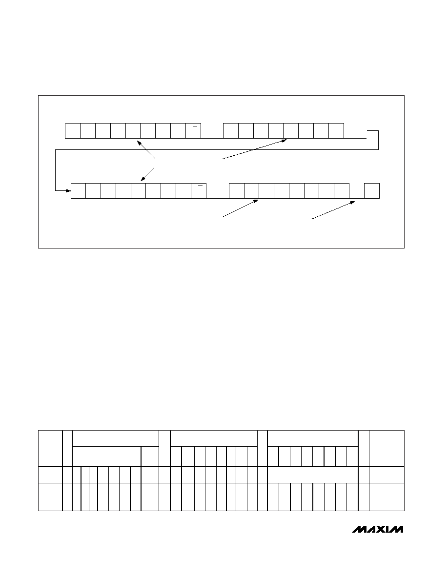
Read Cycle
A read command requires 36 clock cycles. In read
mode, the MAX5109 sends the contents of the volatile
and nonvolatile registers to the bus. Reading a register
requires a REPEATED START (Sr) condition. To read a
register first, write a read command (R/W = 0, Figure 8).
Set the most significant 2 bits of the command byte to
10 (C7 = 1 and C6 = 0). Set bits C5 and C4 to read
from either the volatile or nonvolatile register (Table 5).
Set bits C3–C0 to select the desired DAC register
(Table 6). After the command byte, send a Sr condition
followed by the address of the device (R/W = 1). The
MAX5109 then acknowledges and sends the data to
the bus.
Nonvolatile, Dual, 8-Bit DACs with 2-Wire Serial
Interface
12
______________________________________________________________________________________
S0
1
0
A3
A2
A1
A0
A3
A2
A1
A0
1
0
NV
V
R3R2R1R0
C7
C6
C5
C4
C3
C2
C1
C0
Sr
0
1
0
MSB
LSB
MSB
LSB
MSB
ACK
NACK
R/W
= 1
D7
D6
D5
D4
D3
D2
D1
D0
P
MSB
LSB
ADDRESS AND COMMAND BYTES GENERATED BY MASTER DEVICE
DATA BYTE GENERATED BY MAX5109
NACK GENERATED BY
MASTER DEVICE
R/W
= 0
Figure 8. Example Read Word Data Sequence
ADDRESS BYTE
COMMAND BYTE
DATA BYTE
START
R/
W
C
7
C
6
C
5
C
4
C
3
C
2
C
1
C
0
D
7
D
6
D
5
D
4
D
3
D
2
D
1
D
0
STOP
Master
SDA
S0 1 0
A
3
A
2
A
1
A
0
C
7
C
6
N
V
R
3
R
2
R
1
R
0
D7–D0
P
Slave
SDA
A
C
K
A
C
K
A
C
K
Table 1. Write Operation
相关PDF资料 |
PDF描述 |
|---|---|
| VE-BN1-MU-F3 | CONVERTER MOD DC/DC 12V 200W |
| AD829AQ | IC VIDEO OPAMP HS LN 8-CDIP |
| 4-1877846-4 | PLUG 6POS 0 DEG GRY/YEL 4.0-5.2 |
| 3-1877846-8 | PLUG 6POS 0 DEG BLK/YEL 4.0-5.2 |
| AD8013ARZ-14-R7 | IC AMP VID SGL SUPP LP 14SOIC TR |
相关代理商/技术参数 |
参数描述 |
|---|---|
| MAX510ACPE | 功能描述:数模转换器- DAC RoHS:否 制造商:Texas Instruments 转换器数量:1 DAC 输出端数量:1 转换速率:2 MSPs 分辨率:16 bit 接口类型:QSPI, SPI, Serial (3-Wire, Microwire) 稳定时间:1 us 最大工作温度:+ 85 C 安装风格:SMD/SMT 封装 / 箱体:SOIC-14 封装:Tube |
| MAX510ACPE+ | 功能描述:数模转换器- DAC 8-Bit 4Ch Precision DAC RoHS:否 制造商:Texas Instruments 转换器数量:1 DAC 输出端数量:1 转换速率:2 MSPs 分辨率:16 bit 接口类型:QSPI, SPI, Serial (3-Wire, Microwire) 稳定时间:1 us 最大工作温度:+ 85 C 安装风格:SMD/SMT 封装 / 箱体:SOIC-14 封装:Tube |
| MAX510ACWE | 功能描述:数模转换器- DAC Integrated Circuits (ICs) RoHS:否 制造商:Texas Instruments 转换器数量:1 DAC 输出端数量:1 转换速率:2 MSPs 分辨率:16 bit 接口类型:QSPI, SPI, Serial (3-Wire, Microwire) 稳定时间:1 us 最大工作温度:+ 85 C 安装风格:SMD/SMT 封装 / 箱体:SOIC-14 封装:Tube |
| MAX510ACWE+ | 功能描述:数模转换器- DAC 8-Bit 4Ch Precision DAC RoHS:否 制造商:Texas Instruments 转换器数量:1 DAC 输出端数量:1 转换速率:2 MSPs 分辨率:16 bit 接口类型:QSPI, SPI, Serial (3-Wire, Microwire) 稳定时间:1 us 最大工作温度:+ 85 C 安装风格:SMD/SMT 封装 / 箱体:SOIC-14 封装:Tube |
| MAX510ACWE+T | 功能描述:数模转换器- DAC 8-Bit 4Ch Precision DAC RoHS:否 制造商:Texas Instruments 转换器数量:1 DAC 输出端数量:1 转换速率:2 MSPs 分辨率:16 bit 接口类型:QSPI, SPI, Serial (3-Wire, Microwire) 稳定时间:1 us 最大工作温度:+ 85 C 安装风格:SMD/SMT 封装 / 箱体:SOIC-14 封装:Tube |
发布紧急采购,3分钟左右您将得到回复。