- 您现在的位置:买卖IC网 > PDF目录11583 > MAX5941AESE+ (Maxim Integrated Products)IC IEEE 802.3AF-COMP POE 16-SOIC PDF资料下载
参数资料
| 型号: | MAX5941AESE+ |
| 厂商: | Maxim Integrated Products |
| 文件页数: | 2/24页 |
| 文件大小: | 0K |
| 描述: | IC IEEE 802.3AF-COMP POE 16-SOIC |
| 产品培训模块: | Lead (SnPb) Finish for COTS Obsolescence Mitigation Program |
| 标准包装: | 50 |
| 控制器类型: | 以太网供电控制器(POE) |
| 接口: | IEEE 802.3af |
| 电源电压: | 48V |
| 电流 - 电源: | 1mA |
| 工作温度: | -40°C ~ 85°C |
| 安装类型: | 表面贴装 |
| 封装/外壳: | 16-SOIC(0.154",3.90mm 宽) |
| 供应商设备封装: | 16-SOIC |
| 包装: | 管件 |
MAX5941A/MAX5941B
IEEE 802.3af-Compliant Power-Over-Ethernet
Interface/PWM Controller for Power Devices
10
______________________________________________________________________________________
MAX5941A/MAX5941B
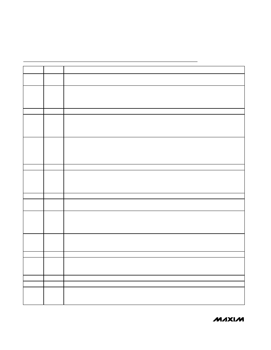
Pin Description
PIN
NAME
FUNCTION
1V+
High-Voltage Startup Input. Referenced to V-. Connect directly to an input voltage range between 18V to 67V.
Connects internally to a high-voltage linear regulator that generates VCC during startup. Tie V+ to GND.
2VDD
Line Regulator Input. Referenced to V-. VDD is the input to the linear regulator that generates VCC. For
supply voltages less than 36V, connect VDD and V+ to the supply. For supply voltages greater than 36V,
VDD receives its power from the tertiary winding of the transformer and accepts voltages from 13V to 36V.
Bypass VDD to V- with a 4.7F capacitor.
3
OPTO
Optocoupler Input. Referenced to V-. The control voltage range on this input is 2V to 3V.
4
SS_SHDN
Soft-Start Timing Capacitor Connection. Referenced to V-. Ramp time to full current limit is approximately
0.45ms/nF. Bypass with a minimum 10nF capacitor to V-. A 2.4V reference voltage appears across the
capacitor. Disable the PWM controller by pulling SS_SHDN below 0.25V. Tie to PGOOD to enable PWM
controller automatically from the PD interface.
5
UVLO
Undervoltage Lockout Programming Input for Power Mode. Referenced to VEE. When UVLO is above its
threshold, the device enters the power mode. Connect UVLO to VEE to use the default undervoltage lockout
threshold. Connect UVLO to an external resistor-divider to define a threshold externally. The series
resistance value of the external resistors must add to 25.5k
(±1%) and replaces the detection resistor. To
keep the device in undervoltage lockout, pull UVLO between VTH,G,UVLO and VREF,UVLO.
6
RCL
Classification Setting. Referenced to VEE. Add a resistor from RCL to VEE to set a PD class (see Tables 1 and 2).
7
GATE
Gate of Internal N-Channel Power MOSFET. Referenced to VEE . GATE sources 10A when the device
enters the power mode. Connect an external 100V ceramic capacitor from GATE to VOUT to program the
inrush current. Pull GATE to VEE to turn off the internal MOSFET. The detection and classification functions
operate normally when GATE is pulled to VEE.
8VEE
Negative Input Power. Source of the integrated isolation N-channel power MOSFET. Connect VEE to -48V.
9
OUT
Output Voltage. Referenced to VEE. Drain of the integrated isolation N-channel power MOSFET. Connect
OUT to V-.
10
PGOOD
Power-Good Indicator Output, Active High, Open Drain. PGOOD is referenced to OUT. PGOOD goes high
impedance when VOUT is within 1.2V of VEE and when GATE is 5V above VEE. Otherwise, PGOOD is pulled
to OUT (given that VOUT is at least 5V below GND). Connect PGOOD directly (no external pullup required)
to SS_SHDN to enable/disable the PWM controller.
11
PGOOD
Power-Good Indicator Output, Active Low, Open Drain. PGOOD is referenced to VEE. PGOOD is pulled to
VEE when VOUT is within 1.2V of VEE and when GATE is 5V above VEE. Otherwise, PGOOD goes high
impedance.
12
GND
Ground. Referenced to VEE. GND is the positive input power. Connect to V+.
13
CS
Current-Sense Input. Referenced to V-. Turns power switch off if VCS rises above 465mV for cycle-by-cycle
current limiting. CS is also the feedback for the current-mode controller. CS connects to the PWM controller
through a leading-edge blanking circuit.
14
V-
V- is the ground terminal of the PWM Controller. Connect to OUT.
15
NDRV
Gate Drive. Referenced to V-. Drives a high-voltage external N-channel power MOSFET.
16
VCC
Regulated IC Supply. Referenced to V-. Provides power for MAX5941_. VCC is regulated from VDD during
normal operation and from V+ during startup. Bypass VCC with a 10F tantalum capacitor in parallel with a
0.1F ceramic capacitor to V-.
相关PDF资料 |
PDF描述 |
|---|---|
| PIC16LF1904-E/MV | MCU 7KB FLASH 256B RAM 40UQFN |
| MAX5941BCSE+ | IC IEEE 802.3AF-COMP POE 16-SOIC |
| PIC24F04KA201-I/P | IC PIC MCU FLASH 512KX4 20-PDIP |
| MAX5941ACSE+ | IC IEEE 802.3AF-COMP POE 16-SOIC |
| PIC16LF1829-E/SO | MCU PIC 14KB FLASH 20-SOIC |
相关代理商/技术参数 |
参数描述 |
|---|---|
| MAX5941AESE+ | 功能描述:输入/输出控制器接口集成电路 IEEE 802.3af POE Int/PWM Controller RoHS:否 制造商:Silicon Labs 产品: 输入/输出端数量: 工作电源电压: 最大工作温度:+ 85 C 最小工作温度:- 40 C 安装风格:SMD/SMT 封装 / 箱体:QFN-64 封装:Tray |
| MAX5941AESE+T | 功能描述:输入/输出控制器接口集成电路 IEEE 802.3af POE Int/PWM Controller RoHS:否 制造商:Silicon Labs 产品: 输入/输出端数量: 工作电源电压: 最大工作温度:+ 85 C 最小工作温度:- 40 C 安装风格:SMD/SMT 封装 / 箱体:QFN-64 封装:Tray |
| MAX5941AESE-T | 功能描述:电源开关 IC - POE / LAN RoHS:否 制造商:Fairchild Semiconductor 开关数量:Single 开关配置:SPST 开启电阻(最大值):7.3 Ohms 串话: 带宽: 开启时间(最大值):13 ns 关闭时间(最大值):20 ns 切换电压(最大): 工作电源电压:8 V to 26 V 最大工作温度:+ 125 C 安装风格:Through Hole 封装 / 箱体:TO-220F-6 |
| MAX5941BCSE | 功能描述:电源开关 IC - POE / LAN RoHS:否 制造商:Fairchild Semiconductor 开关数量:Single 开关配置:SPST 开启电阻(最大值):7.3 Ohms 串话: 带宽: 开启时间(最大值):13 ns 关闭时间(最大值):20 ns 切换电压(最大): 工作电源电压:8 V to 26 V 最大工作温度:+ 125 C 安装风格:Through Hole 封装 / 箱体:TO-220F-6 |
| MAX5941BCSE+ | 功能描述:输入/输出控制器接口集成电路 IEEE 802.3af POE Int/PWM Controller RoHS:否 制造商:Silicon Labs 产品: 输入/输出端数量: 工作电源电压: 最大工作温度:+ 85 C 最小工作温度:- 40 C 安装风格:SMD/SMT 封装 / 箱体:QFN-64 封装:Tray |
发布紧急采购,3分钟左右您将得到回复。