- 您现在的位置:买卖IC网 > PDF目录11583 > MAX5941AESE+ (Maxim Integrated Products)IC IEEE 802.3AF-COMP POE 16-SOIC PDF资料下载
参数资料
| 型号: | MAX5941AESE+ |
| 厂商: | Maxim Integrated Products |
| 文件页数: | 5/24页 |
| 文件大小: | 0K |
| 描述: | IC IEEE 802.3AF-COMP POE 16-SOIC |
| 产品培训模块: | Lead (SnPb) Finish for COTS Obsolescence Mitigation Program |
| 标准包装: | 50 |
| 控制器类型: | 以太网供电控制器(POE) |
| 接口: | IEEE 802.3af |
| 电源电压: | 48V |
| 电流 - 电源: | 1mA |
| 工作温度: | -40°C ~ 85°C |
| 安装类型: | 表面贴装 |
| 封装/外壳: | 16-SOIC(0.154",3.90mm 宽) |
| 供应商设备封装: | 16-SOIC |
| 包装: | 管件 |
MAX5941A/MAX5941B
IEEE 802.3af-Compliant Power-Over-Ethernet
Interface/PWM Controller for Power Devices
______________________________________________________________________________________
13
MAX5941A/MAX5941B
The PSE determines the class of a PD by applying a volt-
age at the PD input and measures the current sourced
out of the PSE. When the PSE applies a voltage between
12.6V and 20V, the MAX5941A/MAX5941B exhibit a cur-
rent characteristic with values indicated in Table 2. The
PSE uses the classification current information to classify
the power requirement of the PD. The classification cur-
rent includes the current drawn by the 25.5k
detection
signature resistor and the supply current of the
MAX5941A/MAX5941B so that the total current drawn by
the PD is within the IEEE 802.3af standard figures. The
classification current is turned off whenever the device is
in power mode.
Power Mode
During power mode, when VIN rises above the
undervoltage lockout threshold (VUVLO,ON), the
MAX5941A/ MAX5941B gradually turn on the internal N-
channel MOSFET Q1 (see Figure 2). The MAX5941A/
MAX5941B charge the gate of Q1 with a constant current
source (10A, typ). The drain-to-gate capacitance of Q1
limits the voltage rise rate at the drain of MOSFET, there-
by limiting the inrush current. To reduce the inrush cur-
rent, add external drain-to-gate capacitance (see the
Inrush Current section). When the drain of Q1 is within
1.2V of its source voltage and its gate-to-source voltage is
above 5V, the MAX5941A/MAX5941B assert the PGOOD/
PGOOD outputs. The MAX5941A/MAX5941B have a wide
UVLO hysteresis and turn-off deglitch time to compensate
for the high impedance of the twisted-pair cable.
Undervoltage Lockout
The MAX5941A/MAX5941B operate up to a 67V supply
voltage with a default UVLO turn-on set at 39V and a
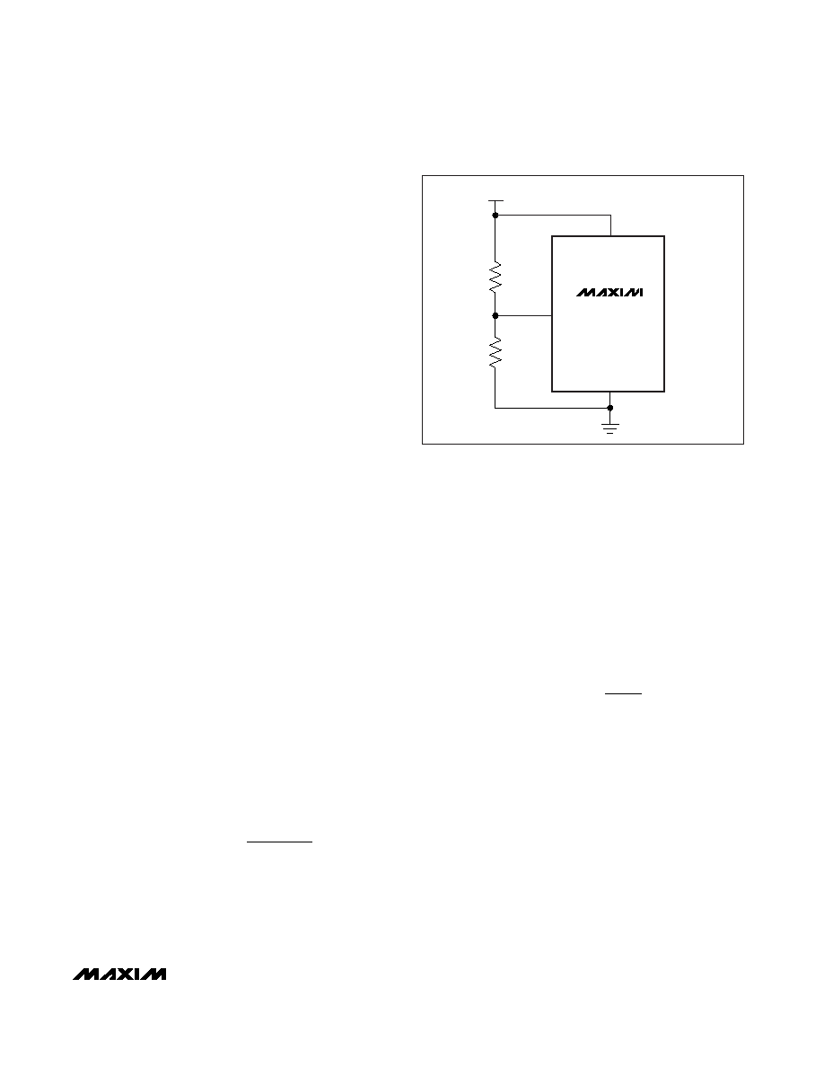
UVLO turn-off set at 30V. Adjust the UVLO threshold
using a resistor-divider connected to UVLO (see Figure
3). When the input voltage is above the UVLO threshold
(VUVLO,ON), the IC is in power mode and the MOSFET is
on. When the input voltage goes below the UVLO thresh-
old (VUVLO,OFF) for more than tOFF_DLY, the MOSFET
turns off.
To adjust the UVLO threshold, connect an external
resistor-divider from GND to UVLO and from UVLO to
VEE. Use the following equations to calculate R1 and
R2 for a desired UVLO threshold:
R1 = 25.5k
- R2
where VIN, EX is the desired UVLO threshold. Since the
resistor-divider replaces the 25.5k
PD detection resis-
tor, ensure that the sum of R1 and R2 equals 25.5k
±1%. When using the external resistor-divider, the
MAX5941 has an external reference voltage hysteresis of
20% (typ). In other words, when UVLO is programmed
externally, the turn-off threshold is 80% (typ) of the new
UVLO turn-on threshold.
Inrush Current Limit
The MAX5941A/MAX5941B charge the gate of the inter-
nal MOSFET with a constant current source (10A, typ).
The drain-to-gate capacitance of the MOSFET limits the
voltage rise rate at the drain, thereby limiting the inrush
current. Add an external capacitor from GATE to OUT
to further reduce the inrush current. Use the following
equation to calculate the inrush current:
The recommended inrush current for a PoE application
is 100mA.
PGOOD/
PGOOD Outputs
PGOOD is an open-drain, active-high logic output.
PGOOD goes high impedance when VOUT is within 1.2V
of VEE and when GATE is 5V above VEE. Otherwise,
PGOOD is pulled to VOUT (given that VOUT is at least 5V
below GND). Connect PGOOD to SS_SHDN to enable the
PWM controller. No external pullup resistor is required.
PGOOD is an open-drain, active-low logic output.
PGOOD is pulled to VEE when VOUT is within 1.2V of VEE
and when GATE is 5V above VEE. Otherwise, PGOOD
goes high impedance.
II
x
C
INRUSH
G
OUT
GATE
=
Rk
x
V
REF UVLO
IN EX
225 5
=
.
,
R1
UVLO
GND
VEE
R2
VIN = 24V TO 60V
MAX5941A
MAX5941B
Figure 3. Setting Undervoltage Lockout with an External
Resistor-Divider
相关PDF资料 |
PDF描述 |
|---|---|
| PIC16LF1904-E/MV | MCU 7KB FLASH 256B RAM 40UQFN |
| MAX5941BCSE+ | IC IEEE 802.3AF-COMP POE 16-SOIC |
| PIC24F04KA201-I/P | IC PIC MCU FLASH 512KX4 20-PDIP |
| MAX5941ACSE+ | IC IEEE 802.3AF-COMP POE 16-SOIC |
| PIC16LF1829-E/SO | MCU PIC 14KB FLASH 20-SOIC |
相关代理商/技术参数 |
参数描述 |
|---|---|
| MAX5941AESE+ | 功能描述:输入/输出控制器接口集成电路 IEEE 802.3af POE Int/PWM Controller RoHS:否 制造商:Silicon Labs 产品: 输入/输出端数量: 工作电源电压: 最大工作温度:+ 85 C 最小工作温度:- 40 C 安装风格:SMD/SMT 封装 / 箱体:QFN-64 封装:Tray |
| MAX5941AESE+T | 功能描述:输入/输出控制器接口集成电路 IEEE 802.3af POE Int/PWM Controller RoHS:否 制造商:Silicon Labs 产品: 输入/输出端数量: 工作电源电压: 最大工作温度:+ 85 C 最小工作温度:- 40 C 安装风格:SMD/SMT 封装 / 箱体:QFN-64 封装:Tray |
| MAX5941AESE-T | 功能描述:电源开关 IC - POE / LAN RoHS:否 制造商:Fairchild Semiconductor 开关数量:Single 开关配置:SPST 开启电阻(最大值):7.3 Ohms 串话: 带宽: 开启时间(最大值):13 ns 关闭时间(最大值):20 ns 切换电压(最大): 工作电源电压:8 V to 26 V 最大工作温度:+ 125 C 安装风格:Through Hole 封装 / 箱体:TO-220F-6 |
| MAX5941BCSE | 功能描述:电源开关 IC - POE / LAN RoHS:否 制造商:Fairchild Semiconductor 开关数量:Single 开关配置:SPST 开启电阻(最大值):7.3 Ohms 串话: 带宽: 开启时间(最大值):13 ns 关闭时间(最大值):20 ns 切换电压(最大): 工作电源电压:8 V to 26 V 最大工作温度:+ 125 C 安装风格:Through Hole 封装 / 箱体:TO-220F-6 |
| MAX5941BCSE+ | 功能描述:输入/输出控制器接口集成电路 IEEE 802.3af POE Int/PWM Controller RoHS:否 制造商:Silicon Labs 产品: 输入/输出端数量: 工作电源电压: 最大工作温度:+ 85 C 最小工作温度:- 40 C 安装风格:SMD/SMT 封装 / 箱体:QFN-64 封装:Tray |
发布紧急采购,3分钟左右您将得到回复。