参数资料
| 型号: | MAX6369KA-T |
| 厂商: | Maxim Integrated Products |
| 文件页数: | 7/10页 |
| 文件大小: | 0K |
| 描述: | IC WATCHDOG TIMER SOT23-8 |
| 产品培训模块: | Lead (SnPb) Finish for COTS Obsolescence Mitigation Program |
| 标准包装: | 1 |
| 类型: | 监视器电路 |
| 监视电压数目: | 1 |
| 输出: | 开路漏极或开路集电极 |
| 复位: | 低有效 |
| 复位超时: | 可调节/可选择 |
| 电压 - 阀值: | 可调节/可选择 |
| 工作温度: | -40°C ~ 85°C |
| 安装类型: | 表面贴装 |
| 封装/外壳: | SOT-23-8 |
| 供应商设备封装: | SOT-23-8 |
| 包装: | 剪切带 (CT) |
| 其它名称: | MAX6369KA-TCT |
�� �
�
�MAX6369–MAX6374�
�Pin-Selectable� Watchdog� Timers�
�completion� of� the� startup� delay� period,� and� no� watch-�
�dog� output� pulses� are� asserted� during� the� startup�
�delay.� When� the� startup� delay� expires,� the� watchdog�
�begins� counting� its� normal� watchdog� timeout� period�
�and� waiting� for� WDI� transitions.� The� startup� delay�
�allows� time� for� the� μP� system� to� power� up� and� fully� ini-�
�tialize� before� assuming� responsibility� for� the� normal�
�watchdog� timer� updates.� Startup� delay� periods� vary�
�between� the� different� devices� and� may� be� altered� by�
�the� logic� control� set� pins.� To� ensure� that� the� system�
�generates� no� undesired� watchdog� outputs,� the� routine�
�watchdog� input� transitions� should� begin� before� the�
�selected� minimum� startup� delay� period� has� expired.�
�The� normal� watchdog� timeout� period� countdown� is� initi-�
�ated� when� the� startup� delay� is� complete.� If� a� valid� logic�
�transition� is� not� recognized� at� WDI� before� the� watchdog�
�timeout� period� has� expired,� the� supervisor� asserts� a�
�watchdog� output.� Watchdog� timeout� periods� vary�
�between� the� different� devices� and� may� be� altered� by�
�the� logic� control� set� pins.� To� ensure� that� the� system�
�generates� no� undesired� watchdog� outputs,� the� watch-�
�dog� input� transitions� should� occur� before� the� selected�
�minimum� watchdog� timeout� period� has� expired.�
�The� startup� delay� and� the� watchdog� timeout� period� are�
�determined� by� the� states� of� the� SET0,� SET1,� and� SET2�
�pins,� and� by� the� particular� device� within� the� family.� For�
�the� MAX6369� and� MAX6370,� the� startup� delay� is� equal�
�to� the� watchdog� timeout� period.� The� startup� and�
�watchdog� timeout� periods� are� pin� selectable� from� 1ms�
�to� 60s� (minimum).�
�For� the� MAX6371� and� MAX6372,� the� startup� delay� is�
�fixed� at� 60s� and� the� watchdog� timeout� period� is� pin�
�selectable� from� 1ms� to� 60s� (minimum).�
�The� MAX6373/MAX6374� provide� two� timing� variations�
�for� the� startup� delay� and� normal� watchdog� timeout.�
�Five� of� the� pin-selectable� modes� provide� startup� delays�
�from� 200μs� to� 60s� minimum,� and� watchdog� timeout�
�t� WD�
�delays� from� 3ms� to� 10s� minimum.� Two� of� the� selectable�
�modes� do� not� initiate� the� watchdog� timer� until� the�
�device� receives� its� first� valid� watchdog� input� transition�
�(there� is� no� fixed� period� by� which� the� first� input� must� be�
�received).� These� two� extended� startup� delay� modes�
�are� useful� for� applications� requiring� more� than� 60s� for�
�system� initialization.�
�All� the� MAX6369–MAX6374� devices� may� be� disabled�
�with� the� proper� logic� control� pin� setting� (Table� 1).�
�Applications� Information�
�Input� Signal� Considerations�
�Watchdog� timing� is� measured� from� the� last� WDI� rising�
�or� falling� edge� associated� with� a� pulse� of� at� least� 100ns�
�in� width.� WDI� transitions� are� ignored� when� WDO� is�
�asserted,� and� during� the� startup� delay� period� (Figure�
�2).� Watchdog� input� transitions� are� also� ignored� for� a�
�setup� period,� t� SETUP� ,� of� up� to� 300μs� after� power-up� or�
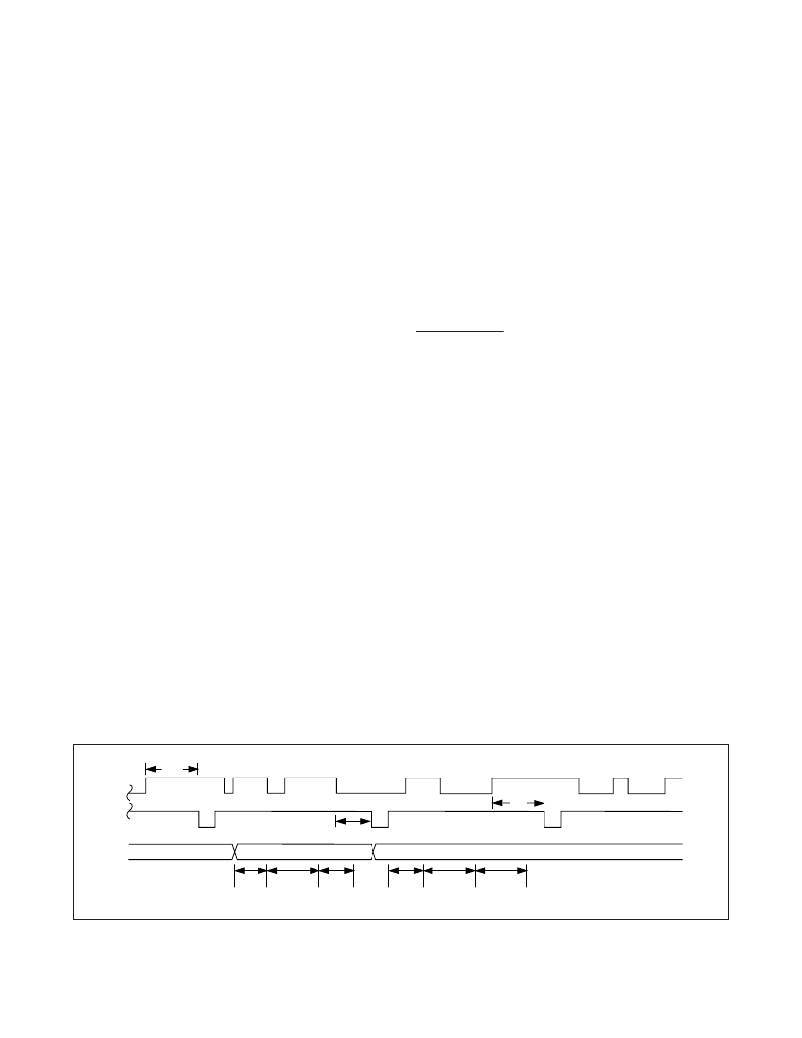
�a� setting� change� (Figure� 3).�
�Selecting� Device� Timing�
�SET2,� SET1,� and� SET0� program� the� startup� delay� and�
�watchdog� timeout� periods� (Table� 1).� Timeout� settings�
�can� be� hard� wired,� or� they� can� be� controlled� with� logic�
�gates� and� modified� during� operation.� To� ensure� smooth�
�transitions,� the� system� should� strobe� WDI� immediately�
�before� the� timing� settings� are� changed.� This� minimizes�
�the� risk� of� initializing� a� setting� change� too� late� in� the�
�timer� countdown� period� and� generating� undesired�
�watchdog� outputs.� After� changing� the� timing� settings,�
�two� outcomes� are� possible� based� on� WDO� .� If� the�
�change� is� made� while� WDO� is� asserted,� the� previous�
�setting� is� allowed� to� finish,� the� characteristics� of� the�
�new� setting� are� assumed,� and� the� new� startup� phase� is�
�entered� after� a� 300μs� setup� time� (t� SETUP� )� elapses.� If�
�the� change� is� made� while� WDO� is� not� asserted,� the�
�new� setting� is� initiated� immediately,� and� the� new� start-�
�up� phase� is� entered� after� the� 300μs� setup� time� elapses.�
�WDI�
�WDO�
�*�
�*�
�*�
�t� WD�
�*�
�*�
�t� WD�
�SET_�
�t� SETUP�
�t� DELAY�
�t� WD�
�t� SETUP�
�t� DELAY�
�t� WD�
�*IGNORED� EDGE�
�Figure� 3.� Setting� Change� Timing�
�Maxim� Integrated�
�7�
�相关PDF资料 |
PDF描述 |
|---|---|
| ABB34DHHR | CONN EDGECARD 68POS .050 DIP SLD |
| UPM2A560MPD | CAP ALUM 56UF 100V 20% RADIAL |
| UPM2A470MPD | CAP ALUM 47UF 100V 20% RADIAL |
| GMA30DTKD-S288 | CONN EDGECARD 60POS .125 EXTEND |
| UPM1K820MPD | CAP ALUM 82UF 80V 20% RADIAL |
相关代理商/技术参数 |
参数描述 |
|---|---|
| MAX636AC/D | 功能描述:直流/直流开关调节器 Preset/Adjustable Output CMOS Inverting Switching Regulators RoHS:否 制造商:International Rectifier 最大输入电压:21 V 开关频率:1.5 MHz 输出电压:0.5 V to 0.86 V 输出电流:4 A 输出端数量: 最大工作温度: 安装风格:SMD/SMT 封装 / 箱体:PQFN 4 x 5 |
| MAX636ACJA | 功能描述:直流/直流开关调节器 RoHS:否 制造商:International Rectifier 最大输入电压:21 V 开关频率:1.5 MHz 输出电压:0.5 V to 0.86 V 输出电流:4 A 输出端数量: 最大工作温度: 安装风格:SMD/SMT 封装 / 箱体:PQFN 4 x 5 |
| MAX636ACPA | 功能描述:直流/直流开关调节器 Preset/Adjustable Invert Switching Reg RoHS:否 制造商:International Rectifier 最大输入电压:21 V 开关频率:1.5 MHz 输出电压:0.5 V to 0.86 V 输出电流:4 A 输出端数量: 最大工作温度: 安装风格:SMD/SMT 封装 / 箱体:PQFN 4 x 5 |
| MAX636ACPA+ | 功能描述:直流/直流开关调节器 Preset/Adjustable Invert Switching Reg RoHS:否 制造商:International Rectifier 最大输入电压:21 V 开关频率:1.5 MHz 输出电压:0.5 V to 0.86 V 输出电流:4 A 输出端数量: 最大工作温度: 安装风格:SMD/SMT 封装 / 箱体:PQFN 4 x 5 |
| MAX636ACSA | 功能描述:直流/直流开关调节器 Preset/Adjustable Invert Switching Reg RoHS:否 制造商:International Rectifier 最大输入电压:21 V 开关频率:1.5 MHz 输出电压:0.5 V to 0.86 V 输出电流:4 A 输出端数量: 最大工作温度: 安装风格:SMD/SMT 封装 / 箱体:PQFN 4 x 5 |
发布紧急采购,3分钟左右您将得到回复。