- 您现在的位置:买卖IC网 > PDF目录67801 > MAX6656MEE+T (MAXIM INTEGRATED PRODUCTS INC) Dual Remote/Local Temperature Sensors and Four-Channel Voltage Monitors PDF资料下载
参数资料
| 型号: | MAX6656MEE+T |
| 厂商: | MAXIM INTEGRATED PRODUCTS INC |
| 元件分类: | 电源管理 |
| 英文描述: | Dual Remote/Local Temperature Sensors and Four-Channel Voltage Monitors |
| 中文描述: | 4-CHANNEL POWER SUPPLY SUPPORT CKT, PDSO16 |
| 封装: | 0.150 INCH, 0.025 INCH PTICH, QSOP-16 |
| 文件页数: | 2/18页 |
| 文件大小: | 256K |
| 代理商: | MAX6656MEE+T |
MAX6655/MAX6656
places constraints on high-frequency noise rejection.
Lay out the PC board carefully with proper external
noise filtering for high-accuracy remote measurements
in electrically noisy environments. Filter high-frequency
electromagnetic interference (EMI) at DXP and DXN
with an external 2200pF capacitor connected between
the two inputs. This capacitor can be increased to
about 3300pF (max), including cable capacitance. A
capacitance higher than 3300pF introduces errors due
to the rise time of the switched-current source.
If necessary, bypass VIN_ pins with any appropriate-
value capacitor for greater noise performance. Do not
put resistance in series with the inputs. Series resis-
tance degrades voltage measurements.
PC Board Layout
1) Place the MAX6655/MAX6656 as close as practical
to the remote diode. In a noisy environment, such as
a computer motherboard, this distance can be 4in to
8in (typ) or more, as long as the worst noise sources
(such as CRTs, clock generators, memory buses,
and ISA/PCI buses) are avoided.
2) Do not route the DXP-DXN lines next to the deflec-
tion coils of a CRT. Also, do not route the traces
across a fast memory bus, which can easily intro-
duce +30°C error, even with good filtering.
Otherwise, most noise sources are fairly benign.
3) Route the DXP and DXN traces parallel and close to
each other, away from any high-voltage traces such
as +12VDC. Avoid leakage currents from PC board
contamination. A 20m
leakage path from DXP to
ground causes approximately +1°C error.
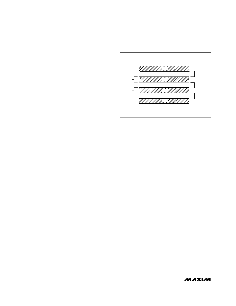
4) Connect guard traces to GND on either side of the
DXP-DXN traces when possible (Figure 5). With
guard traces in place, routing near high-voltage
traces is no longer an issue.
5) Route as few vias and crossunders as possible to
minimize copper/solder thermocouple effects.
6) When introducing a thermocouple, make sure that
both the DXP and the DXN paths have matching
thermocouples. In general, PC board-induced ther-
mocouples are not a serious problem. A copper-sol-
der thermocouple exhibits 3V/°C, and it takes
approximately 200V of voltage error at DXP-DXN to
cause a 1°C measurement error, so most parasitic
thermocouple errors are swamped out.
7) Use wide traces. Narrow traces are more inductive
and tend to pick up radiated noise. The 10-mil
widths and spacings recommended in Figure 5 are
not absolutely necessary (as they offer only a minor
improvement in leakage and noise), but use them
where practical.
8) Note that copper cannot be used as an EMI shield.
Placing a copper ground plane between the DXP-
DXN traces and traces carrying high-frequency
noise signals does not help reduce EMI.
Twisted Pair and Shielded Cables
For remote-sensor distances longer than 8in, or in par-
ticularly noisy environments, a twisted pair is recom-
mended. Its practical length is 6ft to 12ft (typ) before
noise becomes a problem, as tested in a noisy elec-
tronics laboratory. For longer distances, the best solu-
tion is a shielded twisted pair like that used for audio
microphones. For example, Belden #8451 works well
for distances up to 100ft in a noisy environment.
Connect the twisted pair to DXP and DXN and the
shield to GND, and leave the shield’s remote end unter-
minated. Excess capacitance at DX_ limits practical
remote-sensor distances (see Typical Operating
Characteristics).
For very long cable runs, the cable's parasitic capaci-
tance often provides noise filtering, so the recommend-
ed 2200pF capacitor can often be removed or reduced
in value.
Cable resistance also affects remote-sensor accuracy.
A 1
series resistance introduces about +1/2°C error.
Chip Information
TRANSISTOR COUNT: 26,783
PROCESS: BiCMOS
Dual Remote/Local Temperature Sensors and
Four-Channel Voltage Monitors
10
______________________________________________________________________________________
MINIMUM
10MILS
GND
DXN
DXP
GND
Figure 5. Recommended DXP/DXN PC Traces
相关PDF资料 |
PDF描述 |
|---|---|
| MAX6657MSA+ | ±1°C, SMBus-Compatible Remote/Local Temperature Sensors with Overtemperature Alarms |
| MAX6657MSA+T | ±1°C, SMBus-Compatible Remote/Local Temperature Sensors with Overtemperature Alarms |
| MAX6658MSA+ | ±1°C, SMBus-Compatible Remote/Local Temperature Sensors with Overtemperature Alarms |
| MAX6658MSA+T | ±1°C, SMBus-Compatible Remote/Local Temperature Sensors with Overtemperature Alarms |
| MAX6660AEE+ | Remote-Junction Temperature-Controlled Fan-Speed Regulator with SMBus Interface |
相关代理商/技术参数 |
参数描述 |
|---|---|
| MAX6656MEE-TG05 | 功能描述:板上安装温度传感器 RoHS:否 制造商:Omron Electronics 输出类型:Digital 配置: 准确性:+/- 1.5 C, +/- 3 C 温度阈值: 数字输出 - 总线接口:2-Wire, I2C, SMBus 电源电压-最大:5.5 V 电源电压-最小:4.5 V 最大工作温度:+ 50 C 最小工作温度:0 C 关闭: 安装风格: 封装 / 箱体: 设备功能:Temperature and Humidity Sensor |
| MAX6657MSA | 功能描述:板上安装温度传感器 RoHS:否 制造商:Omron Electronics 输出类型:Digital 配置: 准确性:+/- 1.5 C, +/- 3 C 温度阈值: 数字输出 - 总线接口:2-Wire, I2C, SMBus 电源电压-最大:5.5 V 电源电压-最小:4.5 V 最大工作温度:+ 50 C 最小工作温度:0 C 关闭: 安装风格: 封装 / 箱体: 设备功能:Temperature and Humidity Sensor |
| MAX6657MSA+ | 功能描述:板上安装温度传感器 Remote/Local Temperature Sensor RoHS:否 制造商:Omron Electronics 输出类型:Digital 配置: 准确性:+/- 1.5 C, +/- 3 C 温度阈值: 数字输出 - 总线接口:2-Wire, I2C, SMBus 电源电压-最大:5.5 V 电源电压-最小:4.5 V 最大工作温度:+ 50 C 最小工作温度:0 C 关闭: 安装风格: 封装 / 箱体: 设备功能:Temperature and Humidity Sensor |
| MAX6657MSA+T | 功能描述:板上安装温度传感器 Remote/Local Temperature Sensor RoHS:否 制造商:Omron Electronics 输出类型:Digital 配置: 准确性:+/- 1.5 C, +/- 3 C 温度阈值: 数字输出 - 总线接口:2-Wire, I2C, SMBus 电源电压-最大:5.5 V 电源电压-最小:4.5 V 最大工作温度:+ 50 C 最小工作温度:0 C 关闭: 安装风格: 封装 / 箱体: 设备功能:Temperature and Humidity Sensor |
| MAX6657MSA-T | 功能描述:板上安装温度传感器 RoHS:否 制造商:Omron Electronics 输出类型:Digital 配置: 准确性:+/- 1.5 C, +/- 3 C 温度阈值: 数字输出 - 总线接口:2-Wire, I2C, SMBus 电源电压-最大:5.5 V 电源电压-最小:4.5 V 最大工作温度:+ 50 C 最小工作温度:0 C 关闭: 安装风格: 封装 / 箱体: 设备功能:Temperature and Humidity Sensor |
发布紧急采购,3分钟左右您将得到回复。